The use of guard locking on safety doors has long been a proven technology for protecting machines with overtraveling movements. Guard locking ensures that the safety door cannot be opened until the machine has come to a complete stop. Assessing this type of safety system is anything but simple according to the currently valid standard. The successor standard promises clear improvements here.
The new EN ISO 14119 standard
The currently valid EN 1088 will soon be superseded by EN ISO 14119. Both standards provide assistance in the assessment of interlocking devices on movable safety guards. In addition to EN ISO 14119, all other valid standards taken into account for assessing the "guard locking" safety function will be introduced briefly below. The "main standard" in connection with safety doors is currently EN 1088, "Safety of machinery - Interlocking devices associated with guards - Principles for design and selection". This standard has existed since 1995 and was most recently supplemented and published in 2005. The date of the standard is now 2008, but only legal adaptations to the modified Machinery Directive have been added. In terms of content, virtually nothing has changed since the initial publication. A fundamental revision of EN 1088 has been in progress for several years. The draft appeared in the year 2011 under a new number - prEN ISO 14119. The final version is scheduled to appear in early 2013. It has again undergone extensive revisions compared to the draft version. Several key changes will be introduced briefly over the course of this article.
Standard assessment of guard locking using a lathe as an example
The path through the standards is to be described completely one time based on a simple example. A lathe, whose main hazard is the rotating main spindle with the clamped workpiece, serves as the example.
In the first step, the risk analysis can be performed according to EN ISO 12100, or according to the respective C standard, EN ISO 23125, for lathes. The analysis reveals that a cover over the hazard area is necessary due to the possibility of parts being thrown out of the machine. It then must be assessed whether an interlocking device on the protective cover suffices or whether a guard locking device must be used here. The standard used for assessment is EN ISO 13855. This standard regulates the calculation of the distance of safety doors from a hazard area. Section 9 of this standard describes the required minimum distance for a safety device so that no hazard can occur after the door is opened during an overtraveling movement. Alternatively, if the distance is not observed, guard locking can be used. It, in turn, must then be selected according to EN 1088, or soon according EN ISO 14119.
According to EN ISO 13855, the minimum distance of the safety guard from the hazard area is calculated using the formula S = K * T + C. S is the minimum distance, K is the approach speed, T is the time until the machine has been put into a safe state (overtravel) and C is the minimum constant to be observed according to the openings in the safety guard so that no hazard area can be reached in a running machine. For our example involving the lathe, the result is that the value 0 can be assumed because the protective cover does not have any openings. The distance from the workpiece to the intended protective cover is 200 mm. With this value, the resulting maximum permissible overtravel time is 0.125 s (K = 1,600 mm/s as constant from the standard), which can be extended by a value required open the cover. This value is assumed to be 0.5 s by the designer of our lathe. Therefore, the maximum permissible overtravel time is 0.625 s. The drive in our example does not meet this value; it does not stop until approx. 1 s has elapsed. Therefore, either the distance must be increased or guard locking must be used.
In our example, guard locking is used that must meet the requirements of EN 1088 and, beginning with the validity of EN ISO 14119, the requirements of this new standard. A key requirement in both standards is that guard locking must be unlocked by energy and locked by spring force (closed-circuit current principle). Only in justified exceptions is it possible to use a different principle. One possible reason for an exception is, for example, that a fire could start in an installation and access to a machine must be ensured for the fire department even in the event of power failure.
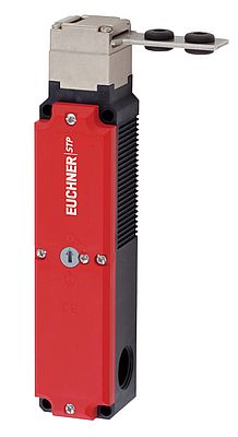
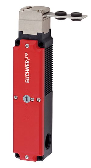
Another possibility intended in EN ISO 14119 for gaining access to the machine in emergency situations is emergency unlocking. This allows the guard locking device to be unlocked without tools in the event of danger. For the lathe example, safety switch STP3 from EUCHNER, which meets the above requirements according to the closed-circuit principle from EN ISO 14119, is suitable for guard locking. The STP is an electromechanical safety switch with guard locking and guard lock monitoring. Its slim design permits simple and space-saving installation. The fiber glass reinforced plastic housing and the high degree of protection (IP67) permit use in very harsh environments. The metal head permits realization of guard locking forces up to 2,500 N. In this application, a switching element with four positively driven NC contacts is installed. Two of them are used for door monitoring and two for solenoid monitoring. The next requirement, which was adopted unchanged in EN ISO 14119, states that the locked position of the guard locking device must be monitored so that the machine can be put into operation only if the guard locking device is actually closed. The associated safety function is monitoring of the locking mechanism of the guard locking device. This must be realized according to the risk analysis. Category 3 according to EN ISO 13849-1 must be achieved in our example, because the required PLr is d. For the selected STP3, contacts 11 - 12 and 31 - 32 are used for this purpose. They both monitor the position of the guard locking solenoid pin.
The technical realization of the safety function is to be assessed in the next step. EN ISO 13849, for example, can be used for this purpose. Several questions arise when guard locking is assessed according to EN ISO 13849-1. Electronic monitoring is usually realized with two channels, such as described in our example above. However, Categories 3 and 4 clearly demand two sensors. Does this mean that two guard locking devices must be used as well? EN ISO 14119 answers this question by stating that fault exclusion on breaking of guard locking is also permissible for PL e or SIL 3. In other words, only one guard locking pin has to be used. It is therefore sufficient to use only one STP3 as the guard locking device.
The diagnostic coverage DC is determined in the next step. For this purpose, the circuit must be designed to detect as many faults as possible. One solution here would be to integrate a second sensor as a door position signal, for example. With the aid of this sensor, it is then possible, depending on evaluation, to find the faults and thereby also to achieve the required diagnostic coverage DC. Alternatively, it is still possible to perform fault exclusion on parts of the safety chain. In this case, the second sensor would not always be necessary. The procedure for fault exclusion is described in the overview "Proven Systems - Proven Safe" from Euchner.
Another question after the safety assessment is the control of a guard locking function. Is this relevant for safety and, if yes, how is assessment performed in this case? The new EN ISO 14119 also answers this question, but unfortunately not quite unequivocally. In a comment, it states that the Performance Level PL is typically lower than the PL of the guard locking position monitoring. This is because a hazard due to failure exists only briefly in most cases. The reason is that the monitoring circuit for the locked position switches the machine off as soon as control of guard locking incorrectly opens the safety guard. Therefore, the hazard posed by an overtraveling machine exists exactly once in most cases. Ultimately, the result certainly will be single-channel control in most practical cases. This must satisfy the demands of PLr from the risk assessment.
By the way, a guard locking device typically includes another safety function: prevention of unexpected start-up of a machine. Since the same components as for guard locking of the safety guard are used for this purpose in most cases, the safety assessment can be adopted from the guard lock monitoring function. This is based on the fact that guard locking devices, e.g. as with safety switch STP, have always included a so-called failsafe locking mechanism. Failsafe locking means that a mechanism prevents the guard locking device from locking without the safety guard being in closed position. For this function, the STP3 includes additional contacts for monitoring the position of the safety guard. A guard locking device thus fulfills very many functions at once.
According to EN ISO 13849-1, it is now necessary to produce a block diagram from the electric circuit based on the structure of the selected category. This not very simple, especially for guard locking devices. The "SISTEMA Cookbooks" from the German Social Accident Insurance (DGUV) provide good instructions for creating the diagram. Additional resources on this topic will appear in future.
In connection with EN ISO 13849, the assessment of a series connection of electromechanical safety switches is also interesting. Whereas the draft of the new standard, prEN ISO 14119, still included assistance on this topic, this material will be omitted in the final version. At the same time, a paper will appear to explain this topic better and more comprehensively. An appendix of a standard cannot address such a complex topic in sufficient detail.
With the future EN ISO 14119, the assessment and use of the proven electromagnetic guard locking devices will be significantly easier overall, because the procedure is described more clearly. Moreover, the new standard includes a simplified assessment of the tampering hazard and a description for the connection to a control system. However, these are only a few of the changes included in EN ISO 14119.
Modern safety solutions simplify assessment
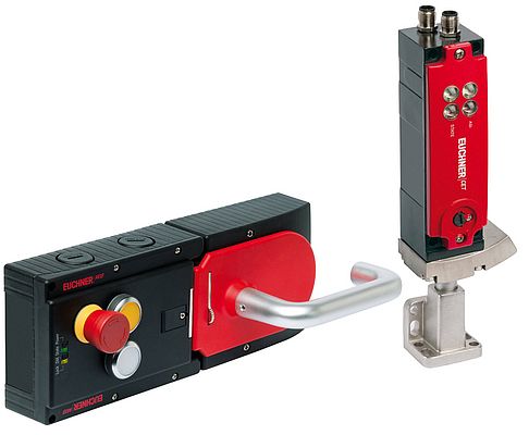
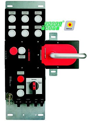
Modern solutions for guard locking devices, such as the Multifunctional Gate Box MGB (system for protecting safety doors) or the CET (transponder-based safety switch with mechanical guard locking) from Euchner, already represent a complete subsystem according to EN ISO 13849-1, because evaluation of the safety signals is already integrated into the device. Consequently, the required block diagram can be produced even more simply. Calculation of the characteristic safety values is simpler, because they can already be provided by EUCHNER. Series connection is also possible with this type of guard locking devices without reducing the PL of the overall circuit. In summary, this is a package that can meet all requirements at once and also fully complies with the new EN ISO 14119.


