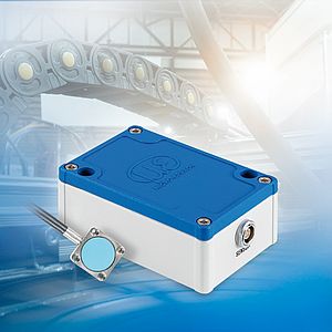
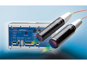
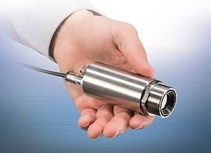
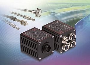
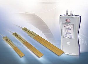
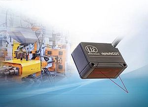
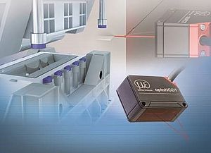
Displacement sensors provide improved comfort, a longer service life of the vehicle and reduced fuel consumption in awide number of applications. Precision eddy current sensors for example are often used, as well as capacitive and inductive sensors, providing unconventional solutions or new approaches to solving sensing problems on passenger cars.
For reduced fuel consumption and improved performance
Eddy current sensors are typically used for optimising conventional combustion engines. However, as there is not much available space in engines these days, special miniature sensors are used. These sensors have to be able to withstand extreme pressures and temperatures.
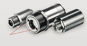
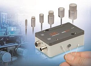
The eddy current sensors measure displacement, distance, position and spacing to sub-micrometre accuracy. These sensors are used for numerous measurement tasks on combustion engines. Special miniature eddy current sensors have been produced, the smallest having an external diameter of just 2mm with an installation length of 4mm. The cable between sensor and controller is also miniaturised, with a cross-section of half a millimetre. In contrast to larger standard sensors, these sensors have a ceramic housing that enables them to withstand high temperatures and pressures. Distances of up to 6m between the controller and sensor can be bridged with the connection cable. In this way, the controller can be installed in the passenger compartment or at the test rig at a safe distance from the engine during measurements. In addition, the operating controls for the controller are located inside the housing. This means that the controller is fully sealed and resistant to oil, water and dirt.
Challenging sensor installation
For any application on an engine, there will be space constraints. The engine housing usually has to incorporate multiple coolant channels. Sensor integration and cable routing are therefore difficult, since no channel can be modified or damaged. At the heart of the engine, at the piston, connecting rod or crank shaft, the cable routing becomes even more difficult, as all parts are moving constantly. However, the desired measurements and values can only be obtained here inside the engine. The sensor also has to withstand a harsh environment for sustained periods: temperatures of up to 200°C, pressures of up to 2,000 bar and contact with fuels, oils or air-fuel mixtures are typical here.
Multiple applications
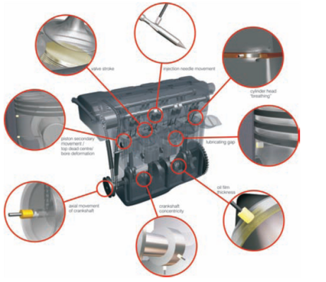
The number of applications is on the increase. For example, the secondary movement of the engine pistons duringtheir different phase strokes needs to be measured. To do this, several sensors are integrated directly inside the pistons, forming a flat surface on the piston wall. The cables are routed along the connecting rod and drive shaft to the outside, viaa swing arm. During operation, for example, when the engine is producing torque under load, it can be established whether the piston in the cylinder has too much 'play' and whether this would adversely affect the service life. The sensors are integrated in the engine housing for measuringthe movement of the piston rings. If, for example, the sensors are moved toanother location in the engine housing, the elongation of the cylinder head gasket during the stroke can be measured. Pressures of up to 50bar are produced forevery ignition of a cylinder, which slightly raises a tightly bolted cylinder head. This movement is compensated for by the cylinder head gasket, which is why itis referred to as “cylinder head gasket breathing”. How far the cylinder head moves is measured by eddy current sensors.
This data provides information about the durability of the gasket and saves customers from fatal engine damage. The measurement of the lubricating gap in the crankshaft bearing is another interesting application. For this, miniature sensors are integrated in the bearing, measuring the distance through the bearing half-shell on the crankshaft. Using this distance, it can be established whether sufficient oil is lubricating the shaft in the bearing. If the film of oil breaks down, the distance to the shaft is almost zero. This is because a certain minimum clearance from the bearing to the shaft is required due to the viscosity of the oil. In the engine itself, sensors can also be used to measure the axial movement of the crankshaft or the oil film thickness on the connecting rod bearing. The top dead centre (TDC) of the piston stroke and the movement of the valves can also be measured.
A new concept provides a completely different approach to the optimisation of combustion engines. Electromagnetic valve trains with fully variable valve controlis one such technology that increases efficiency and reduces fuel consumption in internal combustion engines. Compared with conventional valve trains with camshaft, a multitude of extra adjustment parameters such as load control method, exhaust gas return and valve operating mode are produced for the electromagnetic valve gear. Furthermore, there is the option of cylinder deactivation. Experts calculate a potential saving in fuel consumption of 8% to 9% using this technology.
Significant reductions of the exhaust emissions go hand-in-hand with the fuel savings. With electromagnetic valve gear, the engine valves are controlled by electric actuators rather than by a conventional camshaft. This means the camshaftcan be completely dispensed with. In this way, not only is each valve controlled individually, but also the respective valve lift and valve opening duration are individually optimised. The typical load alternation losses for internal combustion engines are therefore largely avoided.
Dynamic valve lift sensors are used in combination with electric actuators for fast and reliable monitoring of the valvepositions. The valve lift sensor is based on the patented VIP measuring principle, which offers high resolution and linearity, high temperature stability and measuring rates. The VIP sensor provides avery robust mode of operation, while also doing away with the use of permanent magnets. This avoids the disadvantages normally associated with permanent magnets and therefore results in longer service life of the sensor. The valve lift sensor operates in a non-contact manner and is effectively wear-free. A small aluminium ring installed on the actor shaft and which moves in the sensoris used as target for the sensor. The valve lift sensor can be easily modified as an OEM product for customers.


