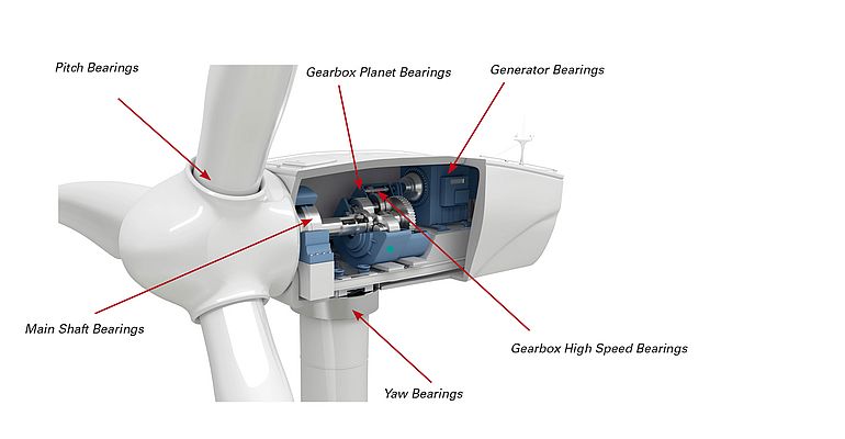
With the growth of the U.S. wind industry and introduction of >1MW turbines, higher loads and increased stresses are impacting mainshaft and gearbox bearing life. Damage and failure modes are occurring sooner than expected, and for many wind farm operators, the cost of unexpected down tower repairs is adding up. As a result, the industry is asking for longer life from mainshaft and gearbox bearings, and manufacturers are stepping up to bring solutions to the market.
“The operator will budget for one or maybe two major overhauls of the turbine over its lifecycle,” said Tony Fierro, application engineer for The Timken Company. “The challenge is that many turbines are requiring a major rebuild within the first seven to 10 years. This means higher O&M spending over the lifecycle of the turbine.”
Costly repairs
What is the financial impact to wind farm operators if a major rebuild is required every seven years?
“If we assume the average life of a turbine is 30 years and the mainshaft and gearbox are being rebuilt every seven years, that means four rebuilds over the turbine lifecycle,” said Fierro. “With an upgraded bearing solution, operators can cut this number in half.”
For example, if a mainshaft and gearbox repair is $300,000 (crane costs included), this represents a total spend of $1.2 million over the lifecycle of the turbine. If these replacements can be cut in half, operators stand to save as much as $600,000 per turbine. For a typical farm operating 100 turbines, O&M savings can approach $60 million over 30 years.
Current design challenges
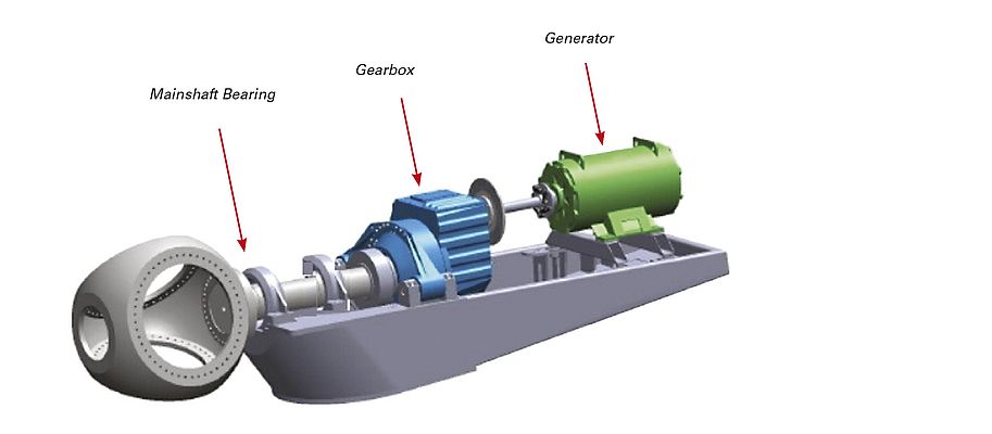
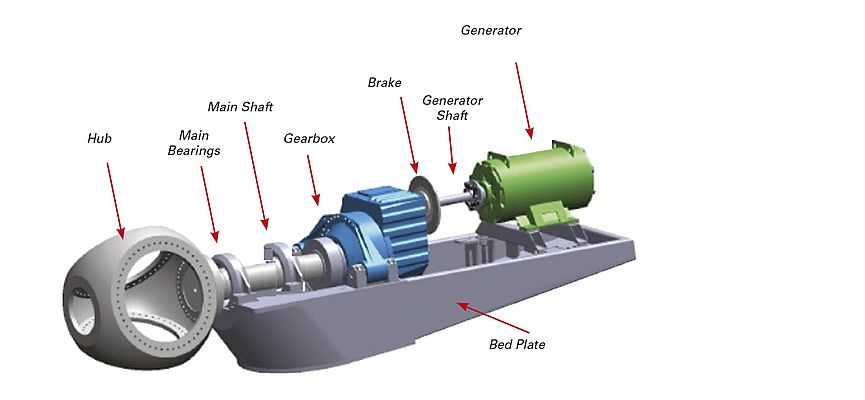
Modular wind turbine designs commonly use two-row spherical roller bearings (SRBs) to support and carry the mainshaft loads. In fact, SRBs dominate the modular turbine market in two different configurations; three- and four-point mount. These configurations are shown in Figure 1.
Three-point design
In the three-point design (left), the mainshaft is supported by the gearbox torque arms and a single SRB in front of the gearbox. This arrangement allows for:
• A shorter nacelle package and reduced turbine mass
• High system deflection and misalignment
While there are advantages to this design, including less nacelle weight and lower initial turbine costs, there are also distinct disadvantages with the two-row SRB mainshaft bearing, and with load transmission into the gearbox.
One issue is that the bearing must support a radial reaction and wind thrust loading on only the downwind (DW) row of rollers. Another problem is that, due to increasing internal clearance as the bearing wears, axial deflection and moment loads are transferred to the gearbox planetary carrier bearings. This additional loading can affect planetary gear meshes and thus, planetary gears and bearing loads.
Common failure modes
Micropitting
The use of a single SRB in the mainshaft position in MW-class turbines has shifted—once the preferred design, operators are now seeking a better solution. A primary driver is the premature damage seen on this type of bearing, mainly due to micropitting (surface fatigue). While there is not an official maximum limit, a conventional ratio of permissible thrust-to-radial loading deemed acceptable for a two-row SRB is approximately 25 percent.
In many large turbines today, actual thrust loads—as high as 60 percent in some instances—are significantly greater than this limit and concerns are increasing over issues related to unseating effects, abnormal load distribution between rows, roller skewing, retainer stress, excessive heat generation and roller smearing. With these high axial loads, only the downwind (DW) row of rollers supports both the radial and thrust loading. Frequently, the upwind (UW) row is completely unloaded creating a less than ideal operating condition.
As a result, mainshaft bearings in three-point mount turbines are experiencing the same common damage modes including micropitting, edge loading, roller end thrust, single piece cage failures, and cage and center guide ring wear as well as debris damage. This is leading to significant field failures early in the lifecycle of turbines.
Inadequate lubrication
Furthermore, mainshaft bearing operating conditions are typically not ideal for lubricant film generation. With a maximum operating speed of approximately 20 rpm, the bearing surface speed and lube film generation often are insufficient to keep the race asperities separated. In addition, changing pitch and yaw moments are constantly shifting the location and direction of the load zone—almost instantaneously. Thus, the formation and the quality of the lubricant film is interrupted.
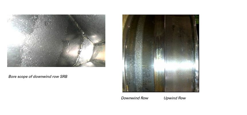
For an SRB in a three-point mount turbine, this situation is accelerated. SRBs are operating under radial clearance, increasing the risk of micropitting or smearing. The early stages of wear are shown in Figure 2 where the distinct wear path in the DW row of rollers will eventually erode the designed contact geometry, leading to higher than predicted raceway stresses and eventually, bearing failure.
Bearing upgrades for existing turbines
Wear-resistant bearings
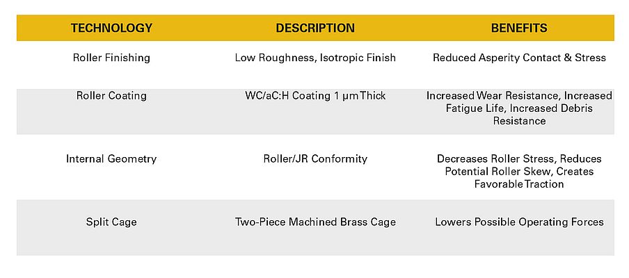
For a direct interchange to existing turbine fleets, Timken developed a Wear Resistant (WR) SRB that utilizes engineered surface technology in combination with enhanced surface finishes. The WR bearings protect raceways against micropitting by significantly reducing the shear stresses and asperity interactions. The engineered surface is a durable and unique tungsten carbide/amorphous hydrocarbon coating (WC/aC:H).
These coatings are two-to-three times harder than steel, one-to-two micrometers thick and have low friction coefficients when sliding against steel. With an advanced engineered surface on the roller, the coating is designed to polish and repair debris damaged raceways during operation. This enhanced surface finish also increases lubricant film thickness, meaning more efficient separation of the asperity contacts. Combined, these improvements reduce the shear stresses that cause wear. Additional features and benefits are summarized in Figure 3.
Conclusion
As bearings perform their mission-critical function inside today’s MW-class turbines, dynamic and unpredictable stresses are causing untimely, expensive repairs. For the benefit of the wind industry moving forward, the reliability of mainshaft bearings must be improved. Market demand is driving the development of new solutions for retrofitting single SRBs in a three-point mount arrangement, including wear-resistant SRBs and a pre-loaded TRB design.


