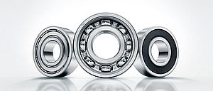
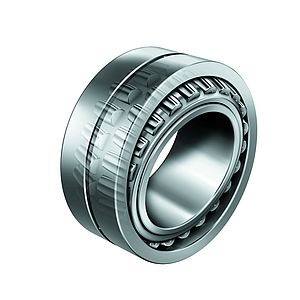
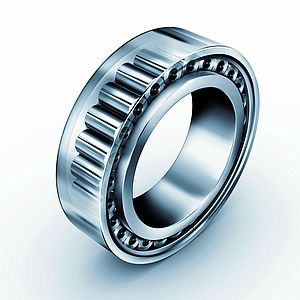
For developers, reducing friction in internal combustion engines is now a high priority. By replacing plain bearings in the engine with rolling bearings, significant advantages can be gained, including reductions in CO2 emissions.
In the push to develop more efficient vehicle drive systems, minimising friction in drive train components is critical. Replacing sliding bearings with rolling bearings, for example, can provide significant improvements in energy efficiency.
Despite these potential benefits, rolling bearings, which were once widespread in engine designs, have been largely superseded by plain bearings. However, recent developments in rolling bearings suggest that it is perhaps now time for engine developers to re-evaluate their choice of bearings.
Due to its sheer size and the distribution of friction, the most obvious starting point on an engine is the crankshaft, with its main and conrod bearings. The number of bearings on the latest engine camshafts makes it particularly interesting to consider the potential for reducing friction there. Also, as the use of balancer shafts in passenger cars is becoming more widespread – in order to improve a vehicle’s noise, vibration and harshness (NVH) rating – the rolling bearing concept and its friction-reduction potential must be evaluated under these specific load and operating conditions.
Rolling bearings for the crankshaft
In volume car production, substituting crankshaft plain bearings (main bearings plus crank pin bearings) with rolling bearings is currently not well established. Previous attempts at this have been rejected for various reasons. However, given the current debate on vehicle CO2 emissions, efforts have now resumed in this area.
Besides lower friction levels, roller-mounted crankshafts are expected to reduce the need for pressurised oil flow. In addition, because of their better dry running characteristics and lower lubricating oil requirements, rolling bearing crankshafts are more suited to an increased number of engine start-stop operations.
In the case of an unsplit crankshaft with integrated rolling bearings, the shaft material must not only satisfy the usual requirements for the crankshaft but must also be suitably prepared as a rolling bearing raceway. The bearing cages and outer races need to be split. The steel for such outer races must not only provide high rolling contact fatigue and durability, but must also be easy to machine and forge, and low cost.
As well as the bearing life calculation, another key factor in bearing design is the identification of suitable clearances. Adequate minimum clearance must be guaranteed in all operating conditions, while the clearance also has a dramatic effect on the engine acoustics. Analytical tools are now available that enable adequate rolling bearing models to be integrated into an overall dynamic system simulation. Practical experience also shows that when it comes to acoustics, an engine with a roller-mounted crankshaft is now a very feasible solution.
Friction-reduction potential
In many respects, the conrod bearings have to satisfy far more stringent technical requirements than the main bearings. Installation space is severely restricted in both radial and axial directions, and extreme peak loads and additional centrifugal forces occur.
The increased wear can be offset by using specific cage designs and coatings, for example, copper/silver coatings and more recently, PVD (Physical Vapour Deposition) coating systems (Triondur).
Friction calculations on individual bearings based on catalogue formulae cannot simply be transferred to this type of application, since the geometrical influences on the bearing, including dynamic tilting, elastic deformation and high dynamic loads are not taken into account in these formulae.
This uncertainty can be resolved by using simulation tools. The friction models used in simulation software are suitable for solid body and mixed friction, as well as elasto-hydrodynamics. The durability of the bearing can be predicted more accurately by integrating the elastic bearing environment. For this reason, rolling bearing manufacturers have invested heavily in developing specific, proprietary software solutions. Schaeffler, for example, uses its in-house developed software, Bearinx, for static calculations, Caba for rolling bearing dynamics and Telos for surface roughness in rolling contacts.
With regard to the design feasibility and the specific challenges for the conrod and the expected friction potential, the technical effort required to implement rolling bearings as the main bearings of the crankshaft is significantly less than with conrod bearings.
Camshaft rolling bearings
In most modern engines, the number of camshaft bearing positions is relatively high and so the potential to reduce friction is considerable. However, compared to the crankshaft, the loads are moderate and so the expected frictional heat relative to the heat transfer capability of the surrounding components (the camshaft and cylinder head) is quite low. This means that when rolling bearings are used, compressed oil does not need to be supplied to the bearings. Indeed, most of the oil acts as a coolant rather than a lubricant.
As far as frictional losses in the camshaft bearings are concerned, both software analysis and torque tests on the cylinder heads demonstrate that, in the case of the plain bearings in the lower speed range, the bearings operate in the mixed friction range. In contrast, at mid-to-high speeds, a separation of the surfaces by a hydrodynamic oil film occurs, which significantly reduces friction.
Conventional camshaft design
One-piece camshafts with small bearing diameters require the bearings to be split (cage and outer ring). To conform to the preferred load direction, the bearing separation plane must be positioned in this area with comparatively little load, so that a reduction in the bearing capacity in the divided area is barely relevant.
Unsplit bearings can be used for assembled camshafts, which have become more popular in recent years. This requires either mounting an inner bearing ring to the shaft or using the main body of the camshaft itself as the rolling bearing raceway – provided that the appropriate material and manufacturing requirements are met.
Friction reduction in tests using camshaft rolling bearings confirms this understanding. In the lower speed range, the losses caused by mixed friction in the plain bearing can be avoided, though at higher speeds the savings potential is limited.
Tunnel camshafts
Despite the friction-related drawbacks of tunnel camshafts, there are still good reasons for using camshafts with larger bearing diameters to allow for an axial assembly into a housing. The reduced number of bearing positions compensates for only part of the increased system-related friction. In this case, the use of rolling bearings to reduce friction looks promising. The unsplit design with thin-walled inner and outer rings that is possible here enables the camshaft design to remain largely unchanged.
Measurements on this type of system show a significantly smaller mixed friction range. The frictional advantage of the rolling bearing, however, is quite constant over speeds in the range 0.2 to 0.5Nm. Therefore, in tunnel camshafts, the higher savings potential combined with comparatively moderate design and manufacturing complexity, results in an extremely favourable cost/benefit ratio.
Acoustics
To analyse the effects of a camshaft rolling bearing on engine acoustics, a four-cylinder, 1.4 litre capacity engine in a compact class vehicle was selected. Due to the comparatively minimal level of acoustic insulation, any unfavourable effects of using rolling bearings should be noticeable. A direct comparison of acoustic measurements in various driving situations yields differences between plain and rolling bearings that in almost all cases are below the perceptible limits.
Optimisation of balancer shaft systems
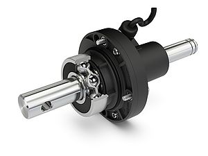
While the need for improvements in fuel consumption is now clearly a hot topic for consumers, minimising NVH levels is also a given. Balancing the free second order mass forces of four-cylinder engines requires two counter-rotating balancer shafts that rotate at twice the crankshaft speed, exerting considerable forces on the cylinder crankcase that quadruple with speed. Due to the number of bearings required as well as the high forces and high speeds involved, the use of rolling bearings to reduce friction appears to be an obvious solution here.
Initial designs of such a rolling bearing arrangement would be based on conventional methods. However, subsequently, the effects of shaft deformations and elasticity of the housing on fatigue durability need to be considered using additional analyses. Other effects on bearing life include oil quality, in terms of its viscosity, contamination and additives, as well as the non-transient peak temperatures that occur during operation. Ultimately, the high peak speeds of balancer shafts in four-cylinder engines often require special bearing and/or cage designs.
For cost reasons, the testing of the bearing design is often initially conducted on a separate test rig, which, for practical reasons, uses four balancer shafts driven in a specific synchronised sequence, in order to compensate for internal inertia forces.
The speed capability of the bearing design, the temperature conditions and the bearing life under various operating conditions are analysed in detail on the test rig. Plain bearing variants can also be directly compared with rolling bearings in terms of required torques, enabling friction reduction potential to be determined.
The reduced friction provided by rolling bearings compared to plain bearings is typically around 50% or higher, depending on design. This is remarkably consistent over test temperatures of between 30 and 120 deg C. Expressed as absolute values, this is more than 1.5kW at an operating temperature of around 100 deg C in the upper speed range. As well as the associated improvements in engine efficiency, this also has positive secondary effects. The heat transfer capability through the surrounding components is often sufficient for the reduced losses in the bearings. This in turn eliminates the need to supply pressurised oil to the bearings. Consequently, omission of the supply bores and reductions in oil pump capacity, as well as oil cooling requirements, are all positive side effects.
Indeed, development engineers at various car manufacturers have confirmed that fuel consumption reductions in the region of two per cent are achievable.
Further potential for optimisation
Eliminating both a pressurised oil supply to the bearings and a raceway on the shaft creates further potential for optimisation. Since the movement of balancer shafts is generated by their imbalance, the force revolves together with the shaft, i.e. the direction of movement relative to the shaft does not change. For the rolling bearings, this means that only those rolling elements located on the side of the imbalanced mass will ever transfer force from the shaft to the housing.
The unstressed rolling elements located in the area opposite the imbalance are kept in contact with the outer race by centrifugal forces and do not come into contact with the shaft. This eliminates the need for a shaft raceway. This area is only required to perform a supporting role when the engine is switched off and the imbalance mass is directed upwards. However, the forces generated in this condition are so low that a significantly reduced raceway width is sufficient. Retaining a certain residual raceway width is also recommended in many applications for acoustic and rolling bearing design reasons.
Reducing the raceway width on only one side will increase the imbalance. In order to restore the target imbalance, mass is removed on the unbalanced side, as close as possible to the axis of rotation, as this increases the amount of mass that can be removed. Continual optimisation here can enable a balancer shaft mass to be reduced by 20-40 per cent compared to existing designs. In the case of a four-cylinder engine, this could mean a reduction in mass of up to 1kg. The mass moment of inertia in the balance shafts is also reduced by a similar percentage, which notably affects the design of the drive train from the crankshaft to the balancer shafts. There are also direct benefits for the acoustics in this part of the drive train, in the form of reduced excitation.
A reduction in the raceway width ultimately has benefits that are specific to rolling bearings. With a cylindrical raceway design and the attempt to eliminate the pressurised oil supply via a supply hole, the possibility of oil mist penetrating the bearing is restricted to a very narrow gap between the race and the outer ring. The new design, however, creates direct, widespread access for oil mist to the roller set. This significantly expands the areas of application for rolling bearings with oil mist supply.


