The volume flow of reciprocating compressors is controlled in many systems today. The spectrum of options ranges from simple bypass control, to variable clearance pocket control, to speed control. In most instances, however, the control range and consequently the energy savings potential is quite limited. Equipment operators fare better with reverse flow control by way of suction valve unloading. Implemented correctly, this method allows the delivery volume to be set from 0 to 100%, while reducing the power consumption to an equivalent degree. A new, all-electric actuator for the valve unloader now makes retrofitting significantly easier for compressors. Fast installation, easy calibration and adjustment by computer, as well as long maintenance intervals lower investment and operating costs in equal measure.
Modern systems engineering is increasingly producing on-demand, requiring flexibility from all components. Given their high power demand, an important factor of reciprocating compressors in particular is setting the optimal volume flow. All-electric hybrid actuator technology made by compressor specialist Hoerbiger now offers entirely new options for efficient control and integration into system control. Installation is simple, merely requiring cables fitted with connectors to be plugged into the actuator or supply unit. Parameterization and calibration are carried out from the control room by computer. The technology behind it has been tried and tested. The text below addresses the technical background of this compact hybrid technology in detail.
Reverse flow control
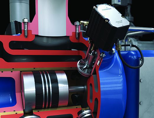
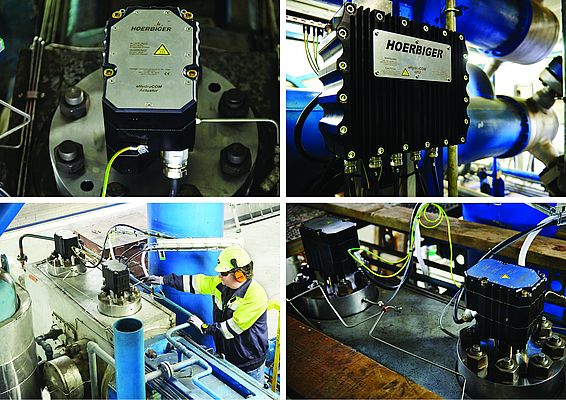
The principle of reverse flow control is relatively simple: the suction valve can be operated by an unloader and kept open, and the unloader is connected to an actuator mounted on the suction cover and moved by the same (Fig. 1).
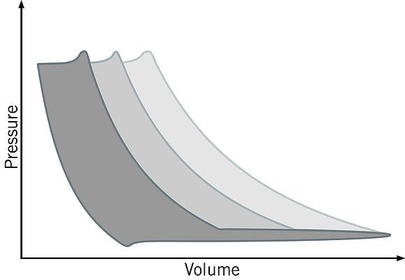
The suction valve is kept open during the compression stroke of a reciprocating compressor, causing a portion of the medium taken in to be pushed back into the suction chamber. Targeted closing of the suction valve at a particular point in time then compresses only the residual amount remaining in the cylinder. As a result, any capacity between 0% and 100% can be variably set via the delayed compression start (Fig. 2).
To provide a better understanding, the sequence of motions will be described for the actuator: at top dead center (TDC), following a compression, the piston moves downward again, and the re-expansion phase begins. Once this phase has ended, the suction valve opens automatically without any outside influence, due to the pressure differential that develops from the piston movement. The actuator presses the unloader in the direction of the suction valve only after the suction valve has opened, in order to establish contact with the suction valve before the piston has arrived at bottom dead center (BDC). Once contact has been established between the sealing element of the suction valve and the unloader, this position is kept constant until the start of the closing process. When the closing time or crank angle, which is dependent on the desired capacity, has been reached, the actuator reduces the force acting on the unloader and the suction valve, ensuring controlled closing of the suction valve. The unloader and sealing element are still in contact until the valve is closed, and the sealing element of the suction valve does not separate from the unloader until it is located in the valve seat. At that time, compression in the cylinder begins. The unloader and actuator carry out a defined idle stroke, and then remain in the end position until the next cycle.
Specific actuator requirements
For reverse flow control to be suitable in practical environments, certain requirements in regard to the actuator must be met to ensure dynamics, reliability, efficiency and a long life during operation. For example, the rate with which the unloader impinges on the sealing element of the already open suction valve must be low, as must be that of the sealing element in the valve seat at the end of the closing step. Additional demands exist as well, be they for safety reasons, ease of operation, or user acceptance. Requirements include a highly dynamic drive able to quickly build and reduce the force, no external cooling measures, the ability to compensate for installation position tolerances and wear during operation, as well as compliance with respect to explosion protection and EMC, while offering a minimal model range.
Hybrid actuator as the solution
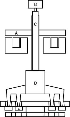
At first glance, several electric drive concepts appear to be possible choices for the task of suction valve operation with the described requirements. Upon closer review, however, various drawbacks eliminate them from practical use. The novel hybrid drive concept made by HOERBIGER combines the advantages of two principles, while satisfying all of the above-described requirements. The concept consists of a solenoid and a spindle drive (refer to Fig. 3). While the solenoid assumes the physical work of the rapid sequences of motion of the unloader, the spindle drive always keeps the solenoid at its optimal operating point. This allows the minimal residual air gap of the solenoid aspired by the design to be utilized, regardless of mechanical wear in the members that transmit the force. The attained high power density without external cooling is comparable to hydraulic systems. One of the key advantages of the hybrid actuator is its ability to vary the relative position of the solenoid with respect to the valve position. During installation, no manual setting of exact lengths with respect to the suction valve is required. In the tolerance range of +/- 5 mm, the height at which the actuator is installed above the suction valve is irrelevant. After the hybrid actuator has been attached to the suction valve cover, an automated reference operation is launched, which ensures that, at the start of regular operation, the open suction valve position corresponds exactly to the nominal minimal residual air gap. Another benefit is that the actuator is permanently maintained at the optimal operating point. The controller additionally detects during operation whether the minimal residual air gap position will be exceeded or not met as a result of wear, thermal expansion or other effects. If the position of the actuator or of the solenoid does not agree with the position of the minimal residual air gap during the phase in which the valve is kept open, the spindle drive is used for readjustment, so that the residual air gap has the correct value during this essential phase.
Control system
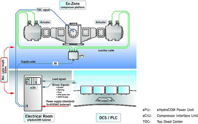
The actuators require modified control to precisely carry out the requisite movement. A power unit supplying the actuators with power is provided for this purpose. The power unit is located in the direct vicinity of the compressor and can control up to 4 actuators. The overall system can consist of as many as 12 power units. A wiring solution, with the related plug connection, developed specifically for the eHydroCOM system, allows simple, and above all time-saving, connection of the actuators to the power unit. The entire system consisting of actuators, power unit and plug connection meets the explosion protection requirements according to classification ExII 2G Ex IIC T4 (Fig. 4).
Sample applications
The electric control system has meanwhile been successfully applied in practice in various industries. The control unit is used in compressors for a natural gas storage facility, a steel mill, and in an ammonia production operation, for example. A single-stage natural gas compressor operates in the natural gas storage facility, using variable suction pressures between 10 and 25 bar for compression to variable final pressures between 30 and 50 bar at 750 revolutions per minute. The flow rate of 2,900 to 10,000 Nm³/h is set to a defined desired value, corresponding to the present demand. At full load, machine output between 150 and 220 kW is required. One of the two cylinders of the compressor, which was already equipped with two electrohydraulic actuators per cylinder, was retrofitted to the new, all-electric eHydroCOM system. This allowed the new and old systems to be compared under identical conditions. The operating data showed no difference between the proven and the new system. In the case of a steel mill, a three-stage nitrogen compressor (Fig. 5) was retrofitted with eight actuators. The suction pressure is 1 bar, and the final pressure is 30 bar, at a volume flow of 7,000 Nm³/h and machine output of 1.1 MW at full load. Compared to the original non-regulated simple on-off control, the compressor capacity can now be steplessly controlled according to highly fluctuating nitrogen demand. The capacity control not only saves significant energy; it also considerably extends the service life and maintenance intervals of the compressors as compared to the on-off control, due to lower material stress.
Additionally, the intermediate pressures were adjusted so that deliberate relief is achieved for high temperature load stages. This provides sufficient reserves over the respective allowed final compression temperature of the stages, even during critical summer months at high suction temperatures. The two-stage N2 compressor (Fig. 6) in a petrochemical plant used to produce ammonia was likewise retrofitted with the electric control system. Originally, diaphragm cylinders were used for on-off control, and variable clearance pockets for regulating the capacity. By nature, this design did not allow precise matching of the capacity to demand, and the nitrogen, which was compressed at high expense to the final pressure but not needed, was recirculated via a bypass valve. The two-stage compressor was retrofitted with four actuators and has a volume flow of 32,000 Nm³/h at a suction pressure of 60 bar and final pressure of 320 bar. The machine output at full load is approximately 2,300 kW. The retrofitted stepless control allows the final pressure of the compressor to be permanently adapted to the process. Due to the rolling change in volume flow, the upstream turbocompressor does not suffer any damaging pressure fluctuations on the pressure side. Thanks to the system's easy and fast installation, the downtime and retrofit costs were low. During ongoing operation, the rolling actuator capacity now results in annual savings of approximately EUR 240,000.
By Dr. Peter Dolovai, Team Leader Development Mechatronics, Research & Development, Hoerbiger Ventilwerke GmbH & Co KG


