Datasheets
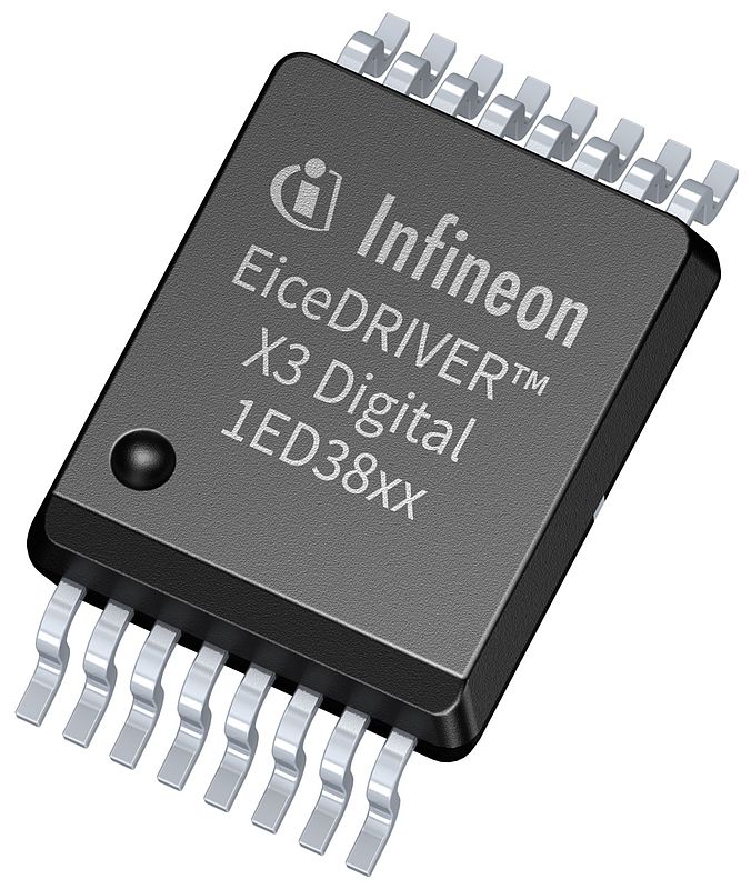
More Design Flexibility, Less Hardware Complexity in Gate Drivers
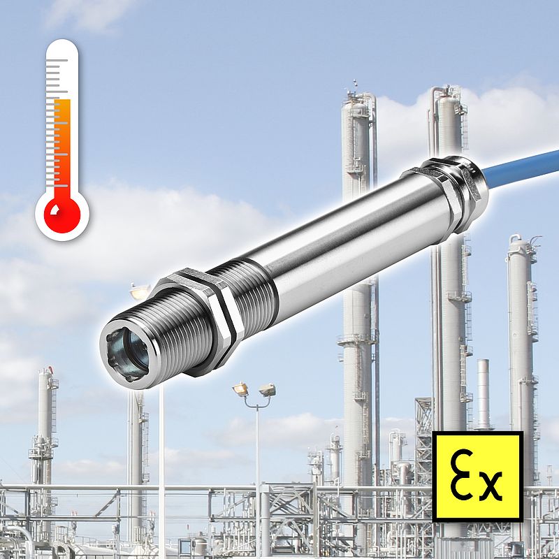
Intrinsically Safe Infrared Temperature Sensor
BMW Chooses Inspekto to Bring AI to the Factory Floor
Automated Quality Control to Increase E-car Throughput
AEO 10.3x38 High-performance Fuse from Schurter
Quick access
News: Renesas & FDT Group2 News: Eurotech & Endress+Hauser3 News: Harting4 News: OPC Foundation & Ness5 Whitepapers6 Article: 3D Modeling and RVI Measurements - Olympus7 Article: Minimising Gas Turbine Varnishing - ExxonMobil8 Interview: Resolve Optics9 Industry Special: Automotive - Vaisala10 Industry Special: Automotive - Keysight11 Industry Special: Automotive - Sandvik12 Industry Special: Automotive - ZF Friedrichshafen13 Schurter14 Industry Special: Automotive - Ametek15 Industry Special: Automotive - REO UK16 Industry Special: Automotive - Schurter17 Interview: Siemens18 Focus IoT & e-Mobility - Mitsubishi19 Focus IoT & e-Mobility - FDT20 Focus IoT & e-Mobility - Futurism Technologies21 Focus IoT & e-Mobility - Omron22 Focus IoT & e-Mobility - KEB Automation23 Identification & Vision Systems - AT24 Identification & Vision Systems - Inspekto25 Article: ADI OtoSense26 Product Focus: ELGi's Screw Air Compressor27 Product News: DC Power Electronics, HMI Devices, Three-axis System28 Product News: Cartridge Seals, Radiation Hard Lenses & Turbine Flow Meters29 Product News: Ultrasonic Flow Meters, Gate drivers, & Infrared Temperature Sensor30 Product News: Micro-Epsilon31Companies in this issue
Calex Electronics Limited30 ExxonMobil Fuels & Lubricants8 FDT Group20 Hans Turck GmbH & Co. KG28 Micro-Epsilon Messtechnik GmbH & Co.KG31 Olympus Europa SE & CO.KG7 SCHURTER AG144 AMETEK GmbH15 Analog Devices GmbH26 Automation Technology GmbH24 Calex Electronics Limited30 Chesterton International Inc.29 ELGi Compressors27 Endress+Hauser Group Services3 ExxonMobil Fuels & Lubricants8 FDT Group20 Futurism Technologies21 Haizol6 Hans Turck GmbH & Co. KG28
Renesas Exhibits at the Virtual European Conference on Optical Communication (ECOC) 2020
The company highlights its optical communication solutions for Datacom and Telecom at the European Conference on Optical Communication 2020
Vision & Identification
Renesas Electronics Corporation is showcasing its portfolio of optical communication products at the virtual European Conference on Optical Communication (ECOC) 2020, which takes place December 7-9.
“Over the last several months, data center, network, and telecom infrastructures have navigated significant increases in the demands and requirements placed on their systems, driven by increasing volumes of high-bandwidth data such as live and on-demand streamed content, the deployment of more AI-based systems, and a worldwide shift to the cloud as more consumers depend on connected systems for their work and daily life,” said Diwakar Vishakhadatta, Vice President of Optical Communication Products at Renesas.
“As cloud and networked services become a mission-critical factor in business’ and consumers’ daily lives, we have expanded our optical communications portfolio, adding elements of our leading microcontroller, timing, and power portfolios, to provide customers a one-stop mixed-signal IC solution with all of the elements they need to scale up for today’s systems and beyond.”
Customers can combine these optical communications series with a variety of Renesas microcontroller (MCU), power management, and timing devices for a solution that supplies all of the components customers need, from optical interconnect to MCU, making it easier and quicker to bring their telecom and data center systems applications to market.
Optical Communications for Datacom
As adoption of PAM4 technology increases in data center and 5G, and link bandwidth transitions to 200G and 400G and beyond, demand is growing for PAM4-based solutions that are smaller and lower cost while maintaining low power and high reliability.
Featuring the industry’s first CMOS-based PAM4 CDR solution, the new HXT14450 CDR with integrated VCSEL driver and the HXR14450 CDR with integrated TIA are designed for 200G and 400G links and are also ideally suited for short range (SR) and Active Optical Cable operation for data centers. The series features significantly lower power and smaller size compared with traditional DSP solutions, as well as higher integration – including an integrated MCU – to further simplify system design. The series is certified for the -40°C to 85°C temperature range, making it ideal for optical communications links in 5G mid- and back-haul infrastructure. The standalone HXC44400 CDR is also available, and customers can combine it with Renesas DML drivers and TIAs to enable 200G long range links.
The lineup of high performance optical signal chain products also includes the HXT45411 family of EML drivers, HXT45430 Silicon-Photonics drivers, HXT44420 family of DML drivers and HXR45400 series TIAs for PAM4 deployments.
Optical Communications for Telecom
With increased demand from service providers, equipment manufacturers, and enterprise networks, network equipment is feeling the strain. Today’s telecom network and 5G infrastructure providers have expanded the deployment of coherent-based 400G equipment in the backbone, while datacenter operators have started to deploy the 400ZR standard defined by the Optical Internetworking Forum (OIF) to meet this need.
Renesas’ 64 GBaud GX76474 driver family and GX36420 series Coherent TIAs combine exceptional analog performance, low power, and high reliability with high bandwidth and configurability to support the telecom industry’s fastest growing segment – coherent optical communications. These new drivers and TIAs support all the key requirements to support the increased demands of longer range communication including:
- Up to 400 Gbps of data speeds using industry-standard 64 GBaud modulation
- Scalable solutions for 32G, 45G, and 64G, enabling customers to optimize either for speed or for power and cost, and to adjust key parameters via Serial Peripheral Interface (SPI)
The GX76474 and GX36420 series also cover all the optical modulator technologies currently on the market, including Lithium Niobate, Indium Phosphide, and Silicon Photonics, as well as both the industry-standard Integrated Coherent Receiver (ICR) and Transmitter Receiver Optical Sub-Assembly (TROSA) configurations.
Availability
Renesas’ complete solution set of industry-leading CDRs, drivers and TIAs is available now.
For more information on Renesas’ datacom portfolio, please visit: www.renesas.com/datacom.
For more information on Renesas’ telecom portfolio, please visit: www.renesas.com/telecom.
FDT Group Welcomes Fuji Electric as Corporate Member
Leading Japanese automation manufacturer to develop FDT 3.0-enabled flowmeters for the energy and environmental markets
Automation, Industry 4.0
FDT Group, an independent, international, not-for-profit industry association supporting the evolution of FDT® Technology, today announced that Fuji Electric has joined its organization as a corporate member. Based in Tokyo, Japan, Fuji Electric develops measurement instrumentation supporting optimal control technologies for seamless integration and data exchange in semiconductor, dam, water purification, sewage treatment, power generation, and district heating and cooling applications.
FDT Group’s mission to drive continued developments in open, standardized universal network/device integration and asset management is innovating the way automation architectures connect and communicate in process, hybrid and discrete manufacturing, including motion control applications. FDT Group membership offers unique advantages for the entire industrial automation industry, including end users, suppliers/developers, service providers, universities, and individuals.
Industrial Internet of Things Ecosystem
FDT corporate members are typically system or device suppliers actively pursuing innovative business model strategies empowered by FDT’s data-centric integration platform supporting modern and diverse architectures. The FDT Industrial Internet of Things (IIoT) Ecosystem consists of Servers, Desktops and Devices. This level of membership provides access to the new FDT 3.0 standard, discounts on the modern development tools and the ability to directly engage with technical and/or marketing working groups to help develop enhancements to the FDT standard, while allowing a first glance at the technology as it evolves to meet market demands.
FDT Group Managing Director Glenn Schulz welcomed Fuji Electric as his organization’s newest member. “Fuji Electric’s membership and interest in Device Type Manager (DTM) development based on the FDT 3.0 solution demonstrates FDT’s pivotal position and strength to meet industry-driven demands for open standards that deliver remote access and IT/OT integration,” Schulz said.
Meeting evolving customers requirements in the automation industry
The FDT 3.0 standard, known as FITS™, recently launched along with the modernized development toolkits known as Common Components to provide automation industry manufacturers with the opportunity to jump-start development to meet evolving customer requirements.
Fuji Electric is a leader in easy and accurate flow measurement devices for the industrial markets. Kazuyuki Yamada, a member of the company’s Measuring Platform Development Group, stated, “By becoming an FDT member, we can enhance our ultrasonic flowmeters with an open and robust integration solution empowering the open exchange of data between automation systems that is essential for our end users. Fuji Electric is dedicated to enhancing integration strategies by offering smart device management solutions meeting the growing demand for seamless integration and improved asset management for critical devices.”
For more information, please visit the FDT Group website: www.fdtgroup.org
Eurotech Collaborates with Orange to Simplify IoT Adoption
Eurotech’s IoT Edge capabilities will be coupled with Orange’s IoT platform to enable end-to-end IoT device and data management for industrial automation, smart transportation, energy management and other use cases
Industry 4.0
Eurotech announces its collaboration with Orange to enable and simplify IoT adoption from edge to cloud. The collaboration aims to combine Eurotech’s IoT Edge capabilities with Orange’s IoT platform Live Objects.
Orange’s IoT platform Live Objects is a secured and resilient IoT SaaS platform hosted in France. Live Objects offers a network agnostic IoT services basement by providing multi-connectivity, enhanced data collection, IoT Fleet management and Data storage & indexing. Live Objects is open to any cloud services (such as Azure, AWS, Google Cloud) and any data sources.
Orange Live Objects can interact with Eurotech’s IoT Edge Components. Eurotech provides rugged, certified Industrial IoT Gateways and edge computers enhanced with Everyware Software Framework (ESF) - Eurotech’s IoT Edge Framework. ESF allows edge computing capabilities like filtering, aggregation and analysis of the specific data coming from IoT devices, and provides a wide set of field protocol libraries to allow maximum integrability and flexibility of gateways to interface with sensors and other devices. The ESF Wires feature allow the building of data pipelines for the visual programming of IoT and edge computing applications.
Management of edge devices
ESF also provides seamless integration with Everyware Cloud (EC), Eurotech’s IoT Integration Hub for the management of edge devices – e.g. providing device provisioning and remote configuration options. Orange’s Live Objects platform interacts with EC through APIs and performs further data analytics, storage and management, and integration with business IT applications. Both Eurotech and Live Objects offer a powerful complementary service for Industry & smart building verticals.
“Eurotech and Orange offer an integrated and completely managed end-to-end IoT solution to address IoT use cases from edge to cloud” states Giuseppe Surace, Eurotech CP&MO. “Eurotech’s edge capabilities provide trusted components – rugged IoT Gateways and Edge computers – and a leading software framework for seamless edge-to-cloud integration for the management of IoT devices deployments, large and small. The strength of Orange’s Live Objects platform, combined with the richness of Eurotech IoT Edge solution, will help pave the way for new advanced IoT cloud and edge computing services for Industry 4.0 & smart building verticals,” adds Giuseppe Surace.
More and more measurement instruments are being ordered online from Endress+Hauser. With the introduction of the new FLEX product segmentation structure, integration of the global E-direct portal into the website and further optimization of the e-commerce area on endress.com, finding and ordering the right products online will be even faster and easier for customers.
The new FLEX segmentation supplements the existing selection options and divides the Endress+Hauser measurement instrument portfolio into four areas according to the needs of the customer. In addition, the endress.com e-commerce area was expanded with useful functions to improve the user experience.
OPC Foundation’s Field Level Communications Initiative reaches significant milestone
Initial release candidate completed and technical paper published
Electronics & Electricity
OPC Foundation announces today that its Field Level Communications Initiative has accomplished a significant milestone in the ongoing project by completing their initial release candidate with the focus on the Controller-to-Controller (C2C) use case. In addition, a technical paper has been published that explains the technical approach and the basic concepts to extend OPC UA to the field level for all use cases and requirements in Factory and Process Automation.
Peter Lutz, Director Field Level Communications of the OPC Foundation says: “We are happy about the progress that our working groups have made over the last months, despite COVID-19 and the associated restrictions. The initial release candidate is a major achievement because it is used to build prototypes and to create test specifications that will be converted to corresponding test cases for the OPC UA certification tool (CTT). Furthermore, it lays the foundation for specification enhancements to also cover the Controller-to-Device (C2D) and Device-to-Device (D2D) use cases in the next step.”
Since the start of the Field Level Communications Initiative in November 2018 more than 300 experts from over 60 OPC Foundation member companies have signed up for the various technical working groups to create the technical concepts and elaborate the specification contents for extending the OPC UA framework for field level communications, including Determinism, Motion, Instruments and Functional Safety.
Thomas Brandl from Bosch Rexroth, who is chairman of the Field Level Communications Initiative’s Steering Committee, comments: “It is remarkable how many companies – including the major automation suppliers and key technology providers from all over the world – are contributing to our initiative and how constructively all the experts work together to advance the common goal of bringing OPC UA to the field level.”
The initial release candidate of the Field Level Communications Initiative consists of four specification parts (Parts 80-83) and focuses on Controller-to-Controller (C2C) communication to exchange process data and configuration data using OPC UA Client/Server and PubSub extensions in combination with peer-to-peer connections and basic diagnostics:
Part 80 (OPC 10000-80) provides an overview and introduces the basic concepts of using OPC UA for field level communications.
Part 81 (OPC 10000-81) specifies the base information model and the communication concepts to meet the various use cases and requirements of Factory and Process Automation.
Part 82 (OPC 10000-82) describes networking services, such as topology discovery and time synchronization.
Part 83 (OPC 10000-83) describes the data structures for sharing information required for Offline Engineering using descriptors and descriptor packages.
A vision to establish OPC UA as a fully scalable, standardized industrial interoperability solution, from sensor to cloud
Progress has also been made by two other working groups of the Field Level Communications Initiative, contributing to a harmonized solution for motion and safety applications:
The Safety Working Group will soon publish Version 2.0 of the OPC UA Safety specification (OPC 10000-15) that includes extensions for OPC UA PubSub and originates out of a cooperation with Profibus International. The Motion Working Group has started work in May 2020 to develop an architecture and common information model for motion devices in cooperation with ODVA and Sercos International. The Advanced Physical Layer (APL) and Time-Sensitive Networking (TSN) are critical important technologies for OPC Foundation in their strategy to bring OPC UA down to the field level. Therefore the following cooperations have been established:
The OPC Foundation has joined the Advanced Physical Layer Project Group (APL) to support the development and promotion of an advanced physical layer (APL) for Industrial Ethernet, suitable for use in demanding applications and hazardous locations in the process industry. The OPC Foundation has established liaisons with IEC SC65C as well as IEEE 802.1 in order to support and align with the IEC/IEEE 60802 TSN Profile for Industrial Automation which is essential to build converged industrial automation networks.
Stefan Hoppe, President OPC Foundation: “Because of its versatility and manufacturer independence, OPC UA is already today used in many different industrial applications and is being supported by various initiatives in process and factory automation. The OPC UA extensions specified by the Field Level Communications Initiative are a key driver to support the vision of the OPC Foundation to establish OPC UA as a fully scalable, standardized industrial interoperability solution, from sensor to cloud.”
Ness Partners With Harpyja to Drive Digital Transformation in Manufacturing and Supply Chain Management Industries
The companies will use their combined expertise in business processes and software engineering to develop and provide innovative products, services and processes in the industrial and supply chain domains
Industrial Equipment & Supplies
Ness, a global provider of digital transformation solutions, has announced a partnership with the business transformation consultancy firm, Harpyja. Together, the companies will use their combined expertise in business processes and software engineering, as well as a common framework rooted in iterative design thinking, to develop and deliver innovative products, services and processes in the industrial and supply chain domains.
“Ness brings a wealth of experience in software product engineering that comes from being a global leader in its field for 20 years,” said Mark Barratt, Chief Executive Officer, Harpyja. “Their end-to-end experience creating strategic proprietary software products and solutions for leading organizations in energy, telematics, 2D/3D digital mapping, supply chain and manufacturing will help us further support our customers with their strategic vision and roadmap.”
Both companies have a successful track record leading organizations through digital transformation, developing business start-ups and pushing international expansion
Ness and Harpyja’s comprehensive experience in cloud enablement, data governance and stewardship, Salesforce, full 3PL and 4PL managed services and best-in-class product and intelligent engineering provides organizations with the means to drive growth, promote continuous optimization and implement technology-based change. .
“Partnering with Harpyja allows us to draw on their decades of strategic, transformational and operational experience across many different verticals in both the private and public sectors,” said Pete Rogers, Executive Vice President and General Manager, Western Europe, Ness. “Both organizations share a relentless vision for innovation, whether that is by helping develop growth or by working side by side with customers to implement technology in a systematic way.”
The Impact of COVID-19 on Manufacturing & Service Industries in China
This whitepaper from Haizol aims to shed light on the overall influence of the pandemic as well as business owner’s confidence levels, coping strategies & proactive strategies
Covid-19
Haizol. Companies throughout China have had their operations influenced to some degree by COVID-19, with small- to mid-sized service and manufacturing enterprises representing more than 190,000 companies in an over $50 billion market. This analysis report, compiled from both Haizol’s own research and existing databases, provides insight into these sectors within China from January to April 2020. Specifically, it highlights how these SMEs have been affected in the context of the global epidemic, and what strategies they are adopting. It enables to compare the impact on manufacturing vs. service industries, as well as the differences in response strategies. It also reveals the differences in the impact on business operations from mid-term to late term of the epidemic, illustrating the recovery of business owner confidence as they enter Q2. Last, it reports proactive targeted strategies that business managers adopted to aid recovery and bounce back.
The Advantages of Digital Pressure Sensors in Industrial Applications
A whitepaper by Martijn Stopel, Sr. Product Design Engineer, Sensata Technologies
Electronics & Electricity
Sensata. Learn when and why it is best to use digital pressure sensors in industrial applications and what types of features can help increase system safety, efficiency and reliability.
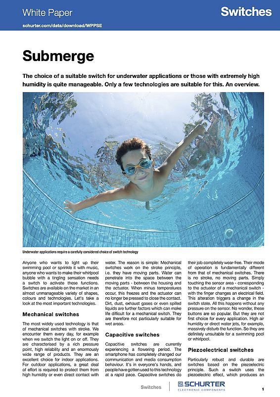
An Overview on the Choice of a Suitable Switch for Underwater Applications
Underwater applications require a carefully considered choice of switch technology
Electronics & Electricity
Schurter. Anyone who wants to light up their swimming pool or sprinkle it with music, anyone who wants to make their whirlpool bubble with a tingling sensation needs a switch to activate these functions. Switches are available on the market in an almost unmanageable variety of shapes, colours and technologies. Let's take a look at the most important technologies.The most widely used technology is that of mechanical switches with stroke. We encounter them every day, for example when we switch the light on or off. They are characterised by a rich pressure point, high reliability and an enormously wide range of products.
Improving Remote Visual Inspection Measurement with 3D Modelling
Advances in 3D modeling enable videoscope inspectors, used for remote visual inspection (RVI), to make more reliable measurements because they can better perceive the actual shape of the object they are measuring
Test & Measurement
One reason we humans can navigate our surroundings so effectively is that we see the world through two forward-facing eyes and our brain constantly compares the two scenes as we move. It detects where each object is located relative to the scene from the other eye. Figures 1a and 1b represent what you see when you close your right eye and left eye respectively. The lateral shift of what we view from one eye to the other is called the parallax effect.
This lateral shift is inversely proportional to the distance from the viewer to the object—meaning the closer it is, the greater the difference in its position from each eye. This also means the “Z” distance is inversely proportional to the lateral shift. Our eyes work with our brains to achieve an understanding of how far away various objects are (a table, a chair, a car, the moon) and how large or small they are. This is fundamentally how stereo measurement works.
Use of Stereo Measurement in Industrial Videoscopes
Industrial videoscopes are devices used in the field of remote visual inspection (RVI). Stereo measuring videoscopes have a charge-coupled device (CCD) imaging sensor and processor (the “brain”) that operate with two lenses (the “eyes”) in the scope’s tip adaptor. The lenses are offset a known distance from each other. Parallax is used to determine the “Z” distance of a point of interest from the two lenses. Figure 2 demonstrates this triangulation.
Prerecorded Data and Measurement Precision
Comparing the parallax of two images can be used to calculate how far away a point of interest is, but the precision of this calculation relies heavily on the prerecorded metrics of the optical system. This means that for a stereo measuring system, the distance between the two lenses in the tip adaptor must be known to a very fine degree.
Videoscope tip adaptors are subjected to very strict tolerances during the manufacturing process. However, their components are housed in an incredibly tight space. The tip adaptor holds two lenses in an area smaller than 6 mm (0.236 in.) or even 4 mm (0.157 in.) in diameter. Because of these miniature sizes, the tolerances are much smaller than are physically possible to control in a manufacturing scenario, and any variance outside the tolerances has a greater effect. Since extremely small physical variations in the components can have large implications on the parallax effect, accounting for and calibrating against these variances is the best strategy.
One way to overcome this limitation is to consider the metrics of the CCD, since it is also part of the parallax calculation. To increase the measurement precision, the distance of the CCD from the lenses and if it is slightly rotated relative to them can also be input into the system. After this is done, that lens system (housed in the tip adaptor) is considered mated to that CCD (housed in the end of the scope). Although videoscope tip adaptors are removable and replaceable, once mated, the stereo lens tip adaptor should always be used with the same videoscope for the sake of higher measurement precision. This is called “one-to-one matching.”
Advantages of Using 3D Modeling
The two major considerations for any measurement system are accuracy and precision. 3D stereo measurement in RVI is no different. So far this discussion on improving accuracy and precision has focused on the videoscope itself. The final piece of this process is the inspector.
With a stereo measuring videoscope, the actual measurements performed are based on points that the inspector places on the two images. The images through the two lenses are almost identical, except for the lateral shift. When the user picks a point on one of the images, the videoscope picks a point on the other image that corresponds to the same point on the object being measured. It then uses all the prerecorded metrics data to calculate the measurement.
Much research and design has gone into 3D stereo measurement to make it as accurate and precise as possible. Because the actual measurement is based on points picked by the inspector, this is where a bottleneck in the measurement system arises. If the inspector is not fully aware of the shape of the object being measured, they may put the point in the wrong place.
Industrial videoscopes are now able to generate 3D models of target objects. The videoscope calculates the distance from the tip adaptor to every pixel on the image. Using the tip adaptor as the anchor in space, the videoscope can then generate a 3D model.
In addition to providing a better understanding of the target object’s shape, the 3D model can show inspectors at a glance the areas of interest that are important to focus on. In Figure 3, there is a 2D image and a 3D image that were taken to identify and measure undercutting in a weld inspection. Undercutting is what happens when there are areas next to the weld that are lower than the base material. It is caused by the intense heat generated by the welding process. In Figure 3, the base material is the flat section to the left of the weld.
Increasing Efficiency with Color Mapping
One way to detect undercutting is to measure the depth at points all along the weld. You can see in the 2D image that there is a white triangle to the left of the weld. This triangle establishes the reference plane. When the depth measurement is performed, they are done in relation to this plane. That is, measurements are made to see how much above or below this plane are the measurement points. If the inspector uses 2D and 3D images alone, multiple measurements are required. A much quicker way to do this is a method called color mapping. Since the videoscope has already calculated the distance values for each pixel on the image, it theoretically already “knows” if there are any spots below the reference plane. With color mapping, this data is used to produce an image (Figure 4), which shows the area below the reference plane in red. The inspector can now focus the measurement on the red areas to locate the deepest undercut value. In this way, 3D modeling can greatly improve the speed of certain measurements.
A videoscope that measures precisely is effective only if it measures the correct point. Advances in 3D modeling enable videoscope inspectors to make more reliable measurements because they can better perceive the actual shape of the object they are measuring. They now know where the point is in real space and are more aware of what the videoscope is measuring. Using features such as color mapping, inspectors can further improve their efficiency, seeing clearly at a glance the critical areas to focus on.
Using High Performance Lubricants to Prevent Gas Turbine Varnishing
Gas turbines are an efficient means of power generation that can be quickly deployed during times of peak demand
Hydraulics & Pneumatics
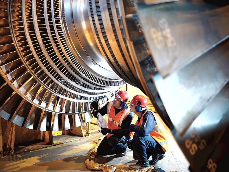
Gas turbines are an efficient means of power generation that can be quickly deployed during times of peak demand. Derek Selby, ExxonMobil’s EAME Industrial Product Technical Advisor, explains how high-performance lubricants can help maintain optimum performance by minimising varnish formation.
In gas turbines today, there has been a shift in equipment trends which has resulted in greater power density, improved efficiency and a reduced CO₂ footprint. These changes have led to longer oil-life for turbine lubricants but, in certain conditions, can also trigger the formation of lubricant related varnish. Left unchecked, this can result in avoidable maintenance and unproductive downtime, which has the potential to generate unnecessary expenditure and damage bottom line performance.
It is broadly considered that the high firing temperatures in turbines, exceeding 1,500°C, can lead to the excessive thermal stress of lubricants and the rapid onset of varnishing formation. This thermal exposure is exacerbated by the start/stop operations that are employed by many gas turbine operators to manage the supply/demand balance of electrical power generation, which results in perpetual cyclic heat soak and cooling during each shut-down sequence.
An industry-wide problem
These types of complications can result in sticking valves and servos, a loss of heat transfer in heat exchangers, filter plugging, lubricant deterioration and potential bearing damage. According to an ExxonMobil survey of 192 gas turbine power plants, running a combined 626 gas turbines, approximately 40% of turbine operators report current or historical issues with oil varnish within the first six years of service.
Turbines with common hydraulic and bearing reservoirs are far more susceptible to issues related to varnish than turbines with segregated reservoirs. Depending on operation and design, these units may suffer from hydraulic valve sticking of air or/and fuel valves, resulting in units failing to start when required and causing unplanned maintenance.
For this reason, early oil varnish detection and prevention is extremely important for common hydraulic/turbine reservoirs, compared with turbines that have separate hydraulic and turbine reservoirs.
Aside from hydraulic valve issues, units may also experience varnish build up on various system parts e.g. bearings, reservoirs, pipe work etc. In particular, this can interfere with the bearing lubrication, and the build of a film on the bearing can interfere with its cooling of the bearing, and result in an increasingly hotter running bearing. This can then result in unscheduled down time and production interruption in order to fix such bearings.
The solution
With such designs and necessity to operate in such conditions, a key element to minimising varnish
formation is the specific lubricant design. It not only needs to withstand high temperatures, and the
resulting thermal degradation, it should ideally also offer:
- Good system protection
- Deposit control and ability to manage any oxidation that occurs
- Excellent load carrying
- Component protection corrosion
- Rapid separation from water and air
- Low volatility characteristics
Mobil SHC 800 Ultra Series have been specifically formulated to provide exceptional protection against thermal/oxidative degradation, with an outstanding RPVOT of typically +3000 min and outstanding keep-clean performance with specific deposit and varnish control.
Mobil SHC 800 Ultra Series also feature the exceptional interfacial properties, in particular steam and water separation, required for modern high performance steam turbines. Mobil SHC 800 Ultra Series’ strong anti-wear performance is designed to meet load-carrying requirements of geared turbines.
ExxonMobil has used its extensive lubricant experience to develop a range of oils suitable for use in even the most severe gas turbine environments. Using synthetic base stock and a specially selected proprietary additive combination, Mobil SHC™ 800 Ultra Series oils have been specifically formulated to provide exceptional protection against thermal/oxidative degradation and outstanding keep-clean performance with specific focus on today’s challenges of deposit and varnish control. They also provide excellent anti-wear properties as well as protection against rust and corrosion, plus superb air release performance and resistance to foaming.
The high performance lubricants also possess superb demulsibility properties with both water and steam, helping to minimise corrosion and the formation of an undesirable stable emulsion. The outstanding air separation feature offered by the oils can also help to prevent oils becoming compressible. If left unchecked, this can reduce the efficiency of hydraulic control systems and potentially lead to damaging cavitation of pumps.
Mobil SHC 800 Ultra Series oils are suitable for applications where a turbine shares a common reservoir with a generator or compressor and gear box. As a result, this can help to increase operator flexibility and reduce inventory.
The performance features of Mobil SHC 800 Ultra Series oils translate into excellent equipment protection, reliable operation, with reduced down-time and extended oil life. These products also
provide the ultimate flexibility to the operator due to the extensive use in a wide variety of turbine types
Tackling varnish formation
The Celanese chemical plant in Belgium was having issues with one of its Siemens SST 060 steam turbines. The unit was suffering from a high level of varnish formation, which resulted in unscheduled downtime and excessive oil consumption. ExxonMobil recommended a switch to Mobil SHC™ 846 Ultra, one of its newly formulated turbine oils, in combination with oil cleaning, flushing and filtration to remove the varnish deposits.
The trial resulted in positive feedback – Celanese was impressed by the used oil analysis data, which showed outstanding protection against varnish build-up and sludge formation. As a result, oil drain intervals were safely extended, which reduced waste oil disposal by 1,500 litres and increased equipment availability. In combination, these offered Celanese a potential benefit of €72,000.
Find out more here.
All the Nuances of Optical Design
Interview with Mark Pontin, Managing Director at Resolve Optics
Vision & Identification
Off-the-shelf versus custom design lenses? Do smaller optical systems mean lower performance? Athermal lenses: the solution for higher temperature applications? Today's industrial applications can seriously put optical design to the test. But finding the best compromise solution is never impossible. Mark Pontin, Managing Director at Resolve Optics, explains how you can get superior optical performance while meeting demanding challenges.
IEN Europe: Resolve Optics is highly experienced at producing machine vision lenses. What are the advantages of your application optimized lenses versus standard off-the-shelf lenses?
M. Pontin: We would never suggest a custom design over an off the shelf (OTS) solution if a suitable OTS lens exists then this is the direction we would point the customer. However, applications where OTS lenses deliver at best a compromise solution are a Resolve Optics specialty. We are highly experienced at producing application optimized machine vision lenses that provide wide fields of view with little or no distortion, optical designs and coatings that are balanced to give best performance at a desired wavelength or waveband and compact lens designs where your target vision application is space limited. We have particular expertise in developing, under OEM contract, fixed and zoom lenses for machine vision applications including parts recognition, precise component placement, automated alignment and placement as well as automated inspection of manufactured components.
Apart from superior optical performance there are other advantages to commissioning a custom design with Resolve Optics such as lens exclusivity to give you a competitive advantage. You will also have security of supply eliminating the risk of a vital lens being discontinued which can happen without notice with OTS lenses.
IEN Europe: Markets are demanding ever-smaller optical systems to make measurements and capture images. Do you think that it is possible to ensure the same performance with a smaller product?
M. Pontin: The size of any lens is subject to the laws of physics. In order to ensure the same performance with smaller lenses you will also need for development of smaller and smaller matched sensors. For example, if you think of the lenses on your mobile phone. Reduction of the camera lens size here has been achieved through the use of very small and very thin molded aspheric elements coupled with some very clever sensor electronics. To use molded lens elements in a product design typically requires a commitment to order in the region of 5,000 lens sets per year to get costs down to a commercially viable level.
For lower volume applications, S-mount or M12 mount lenses are about a small as things get before small batch assembly becomes time consuming and expensive. When you have a space limited application – I would always recommend that you talk to Resolve Optics ahead of the selecting your camera or sensor if possible. This will enable us to advise how much room is likely to be required for the lens which will then give you a better idea of what camera or sensor you can fit within the space envelope.
IEN Europe: Resolve Optics’ radiation hard lenses were used recently in satellite-based video cameras. How important is the space market for your business? Do you see a growth in demand there?
M. Pontin: Over the last 10 -15 years we have been honored to be repeatedly selected by leading space agencies and commercial satellite companies to develop specialist optical systems for them that can withstand the rigors of launch and the hostile environment of space. However, to be honest, lenses for space applications will never make us a fortune as the market is just too small. Of course, as with any new lens design you hope the demand will eventually grow but Resolve Optics does not see this as the main reason for designing and manufacturing lenses for space. We like the challenge of designing lenses that can operate reliably in space.
To make technology work in space is not straight forward, with both mechanical and environmental challenges, such as extreme temperature changes and radiation that can damage electronics and hardware. Space is also very mass sensitive because each gram costs money to launch. As a consequence, we were approached recently by a satellite company that needed a specialist provider who could custom design and manufacture cameras to meet both the unique constraints of spaceflight hardware and the environmental challenges of operating in space for several years. Commercially available camera lenses were not suitable for this application because the glass would increasingly suffer from radiation ‘browning’ – meaning that image quality would gradually deteriorate over the life of the satellite. We were selected to assist with this project because of our expertise in custom designing low mass, high performance lenses using radiation resistant glass that could meet the harsh demands of the space environment.
IEN Europe: A large number of industrial applications require measurements at higher temperatures, how does this affect optical systems? What experience does Resolve have in designing and producing high temperature optical systems?
M. Pontin: Designing optical systems for industrial applications running at elevated temperatures can be challenging. When an optical system heats up the rate of expansion differs depending on the materials used in the design. To avoid an optical system going out of focus at elevated temperatures you must carefully consider the rate of expansion of both optical components and air spaces. Temperature also affects the refractive index of optical materials so this needs to be taken into account as well. Taking into account all these factors allows you to design an athermal optical system. For performance, accuracy and safety reasons - optical systems should be designed to operate at temperatures that are considerably cooler than the high temperature industrial application you wish to monitor. The cooling of such optical systems is most often achieved using cooled air or water running through a supporting jacket.
Over the last decade our engineers and designers have accumulated the expertise to enable us to design and manufacture novel industrial endoscopes that will effectively operate up to 950°C without the need for additional cooling equipment. This has made it possible for our customers to undertake applications including optical inspection inside an engine or operating furnace as well as non-invasive monitoring of high temperature processes including incineration, recycling, smelting and chemical manufacturing.
IEN Europe: Covid-19 is still hitting our societies and economies hard. How is Resolve Optics dealing with the challenges posed by the pandemic?
M. Pontin: Resolve Optics has invested a considerable amount of time and money to ensure that our staff, who cannot work from home, work in a Covid secure environment. At our facility in Chesham, UK only Resolve Optics personnel are allowed to enter the building and certain areas within the facility are restricted to entry only by production or optical testing staff. In line with UK government guidelines – Perspex screens have been erected in areas where it is difficult to maintain the desired 2-metre separation between staff members. Hand sanitizer stations have been installed throughout our offices, corridors and production areas. Taking these measures has enabled our staff to safely continue to design and manufacture our lenses and most importantly maintain timely supply to our customers.
IEN Europe: Covid-19 has also affected the supply chain market. How is Resolve Optics supporting its OEM customer base to guarantee new optical developments and orders are on time?
M. Pontin: Despite the considerable challenges that the pandemic has brought to bear on our business, so far Resolve Optics has not had a problem with our supply chain. However, we are not complacent and proactively monitor the situation on a regular basis. As I mentioned previously Resolve Optics ability to design, develop and manufacture lenses has to date been unaffected by Covid-19 and we are working very hard to ensure it does not affect us as we move into 2021.
Sara Ibrahim
Real-time & Comprehensive Weather Data to Bolster Driver Safety
Vaisala’s digital weather information has been included to Hyundai Motor Company vehicles to provide comprehensive weather data
Hydraulics & Pneumatics
Vaisala announced at TU-Automotive Detroit an agreement with Hyundai Motors to provide Vaisala Infotainment Weather, a digital offering that delivers drivers essential proactive information from in-vehicle infotainment systems about weather and driving conditions.
Markus Melin, Vice President of Vaisala Digital, commented: “With approximately one in every four traffic accidents stemming from inclement weather conditions, our wide-ranging service helps drivers remain aware of weather conditions along their routes and in close proximity to the vehicle’s current location. Even in locations where weather measurements are not easily obtained, our technology is able to predict conditions according to a driver’s route.”
Vaisala Infotainment Weather delivers location-based weather information – like temperature, precipitation, and wind speed – for Hyundai’s LIVE services. Building a successful in-vehicle weather service requires consideration of very dynamic weather conditions combined with the ever-changing position of the car, which demands highly sophisticated methods for local and timely weather data production and delivery.
Advanced road surface condition datasets for automotive use cases
In addition to providing an infotainment weather offering for connected cars, Vaisala Digital, also offers advanced road surface condition datasets for automotive use cases. Vaisala offers industry-leading sensors, a mobile data collection system, and excellent forecasting capabilities that provide real-time calculated driving condition forecasts (including the state of the road’s surface, visibility, and atmospheric weather events affecting driving) to any coordinate point around the globe. Vaisala forecasts are trusted in the winter maintenance industry by road authorities in a number of countries.
“Now that vehicles are increasingly connected, high-quality infotainment weather information is certainly a valuable commodity,” continued Melin. “But leveraging today’s most advanced road weather technologies – beyond forecasting – to provide drivers with actionable information on road surface conditions, prediction of road friction, and other offerings will become invaluable in the future as vehicles with advanced driver assistance systems increasingly integrate onto our roadways around the globe. Accurate and detailed weather-related information and guidance is extremely useful for both drivers and connected vehicles.”
Automotive Cybersecurity: Enabling Safety and Security for the Connected Car
An application story by Hwee Yng Yeo, Keysight Technologies
Hydraulics & Pneumatics
The modern Connected Car runs on software from various sources. According to Code Complete (by Steve McConnell; Cob and Mills, 1990), even the best coding practices produce one coding error per 10,000 lines of code. With about 100,000,000 lines of code in a modern high-end car, this works out to about 10,000 software bugs onboard!
According to Upstream Security’s Global Automotive Cybersecurity Report 2020, the number of known automotive cyber-security incidents almost doubled between 2018 and 2019. The study analyzed 367 publicly reported automotive cyber-attack incidents since 2010, 155 of which are from 2019. These latest figures equate to a 94 per cent year-on-year growth.
The more dramatic hacks and threats to personal safety often make headlines, such as white-hat carjacking with packet codes sent over the internet anywhere in the world. This exposed vulnerability heightens the fear that hackers can hijack autonomous vehicles miles way, with helpless passengers onboard.
The Connected Car is no different from our laptop or mobile phone, containing precious commodity welcomed on the dark web. Seemingly mundane information such as route preferences, credit card payment records, or the driver’s locations, can fetch high prices from seeking bidders.
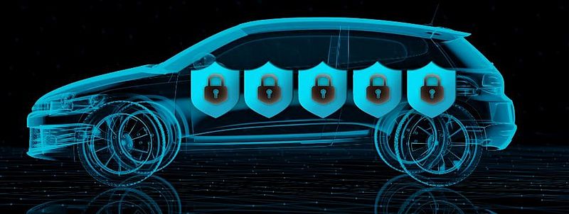
A single cyber hack can cost car makers up to $1 billion, and more losses in reputation and customer trust. That’s why car makers are starting to view cybersecurity very seriously. The industry is considering cybersecurity ratings for cars – the brand or model that sports a five-shield security rating will likely bolster the brand’s value and fetch a premium.
The Connected Car – A Hacker’s Paradise?
A closer look at the sub-systems enabling vehicular communication reveals numerous points of vulnerability (see Figure 1). Hackers can launch various attack paths, ranging from cryptographic attacks at the hardware level, to over-the-air (OTA) protocol attacks. The industry is aware of the need to fortify these at-risk interfaces, there is no official automotive cybersecurity standard all this while.
As the industry awaits official standards, automotive OEMs and subsystem makers are not leaving any loophole to chance. Most of them include cybersecurity risk management in their fleet’s product life cycle (see Figure 2).
One of the ways which the automotive design and test engineers try to secure the car is by using a holistic intrusion protection strategy (see Figure 3). It combines hardware security validation, with software to stress test the potential attack interfaces against a dynamic threats library. As the aim of the automotive cybersecurity developers is to stay steps ahead of the hackers, the engineers must constantly update their test plans and run them against a “live” application and threat intelligence (ATI) library. For example, Keysight operates ATI subscription services spanning years of knowledge gained from attack information.
In the penetration test platform illustrated above, both wireless and wireline interfaces within the car can be tested to validate the robustness of safety-critical components such as ECUs, as well as communication systems for advanced driver assistance systems (ADAS), and vehicle-to-everything (V2X) applications.
Automotive Cybersecurity Pen Test Set-up
A cybersecurity penetration test architecture may comprise these key components (see Figure 4):
• Connectivity gateways - allow both wired and wireless connection to the various automotive DUTs.
• Test management server – lets the white hat engineers manage their test plans, including scanning for vulnerabilities through various reconnaissance scenarios, for example port scanning, fuzz testing, and many more.
• Recon and fuzzing server – the fuzzing plus many other PEN test scenarios are run on this Linux-based server. This is where coding errors and other security loopholes are uncovered, before executing simulated cyberattacks.
• Application & threat intelligence (ATI) library – this is where all captured threats and information are stored. It provides granular application-level visibility and control, geolocation, known-bad IP address blocking, and other threat information.
• Automation – With hundreds of DUTs and thousands of testplans, an intelligent automation platform provides the sanity check for engineers to keep their pen test operations together.
A holistic penetration test platform allows the engineer to examine the plethora of cybersecurity loopholes that may put the driver, passenger, and the marque at risk. No single car maker has an exhaustive list of cybersecurity vulnerabilities. That is one reason why car makers are turning to what their IOT counterparts have been doing – subscribing to secure and dynamic threat intelligence libraries that are available 24x7.
Future-Proofing Automotive Cybersecurity
Even as the white hats build up their arsenal of test plans in the lab, the need to have a robust security strategy is finally garnering the much-needed attention of management teams to rethink automotive cybersecurity. The industry is aware the piecemeal approach to defending the car of the future is no longer sufficient. Enterprise-level automated test platforms involving big data will become increasingly important to help car makers enhance safety and security, as the world moves towards widespread adoption of autonomous driving through ADAS and V2X technologies.
Advocates believe different segments of the automotive industry can leverage these insights to secure not just the individual vehicle, but entire traffic systems. This collective knowledge can help to forge evolving automotive cybersecurity standards to better secure the future of the internet on wheels.
Hwee Yng Yeo, Keysight Technologies
Is Automotive Ready for Hydrogen?
An application story by Mats W Lundberg, sustainable business manager at Sandvik Materials Technology
Hydraulics & Pneumatics
With global sustainability legislations slowly shifting the automotive market away from combustion engines, you’ve probably heard somebody utter “my next car will be electric”. If you haven’t, it’s likely you will soon. However, one fuel source doesn’t fit all. Making the green shift in the automotive market will require other sustainable fuel sources. Here Mats W Lundberg, sustainable business manager at Sandvik Materials Technology, maps out the road towards hydrogen fuel.
The move away from petrol, diesel and hybrid cars can seem like a shifting target. In the UK, legislation to ban the manufacture of such vehicles is being introduced in 2035 — five years before its original target. Canada and Singapore are planning a phase-out by 2040, while Sweden hopes to stop producing diesel-powered vehicles as soon as 2030.
Despite these variations in deadline, global change is happening — and soon. Automakers and drivers alike will need to adjust to a more sustainable future, but how can you decide which resource will power your vehicle?
BEVs versus FCEVs
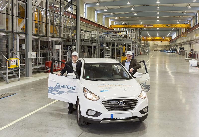
There has been a tendency for the automotive sector to view battery electric vehicles (BEVs) and fuel cell electric vehicles (FCEVs) as competing technologies. While BEVs gain their power from electricity stored in a battery pack that powers the vehicle’s electric motor, FCEVs are powered by fuel cells.
A fuel cell is a device that converts energy stored in molecules into electrical energy. Using hydrogen and oxygen as power, the fuel cell produces water, electricity and heat without creating any emissions other than water vapour. Only oxygen and hydrogen are required to power the fuel cell — the former is readily available in the atmosphere, and the latter can be generated through electrolysis.
There are benefits to both fuel technologies. FCEVs can offer better weight economy, making them effective when powering larger vehicles such as haulage and courier trucks that need to limit unnecessary weight gain. Vehicles that regularly travel long distances or that need to refuel quickly are also more suited to hydrogen. Hydrogen is also a good choice for longer-term storage, since it is a gas that can easily be stored in tanks and containers, while battery lifetime can suffer if the batteries are not charged and discharged correctly.
However, hydrogen’s sustainable future largely relies on the production of green hydrogen — produced through electrolysis that’s powered by renewable resources like offshore wind. Currently, around 96 per cent of hydrogen is generated from fossil fuels, so developments must still be made if FCEVs are going to match the feasibility of BEVs.
A hydrogen future?
Green hydrogen needs to progress further, but its development hasn’t stopped the automotive industry from trialling hydrogen. Across Europe, many projects are already underway to test and deploy hydrogen buses, taxis and other large vehicles, spurring on investment in refuelling stations and other infrastructure that will be critical to the roll-out of FCEVs.
For instance, the Joint Initiative for Hydrogen Vehicles across Europe (JIVE) project seeks to deploy 139 new zero emission fuel cell buses and associated refuelling infrastructure across five European countries. JIVE is co-funded by a 32 million euro grant from the Fuel Cells and Hydrogen Joint Undertaking under the European Union Horizon 2020 framework programme for research and innovation. Planned operating sites include the UK, Belgium, Germany, Italy and Denmark.
Elsewhere, British carmaker Jaguar Land Rover is working on a government-sponsored initiative, Project Zeus, that will develop fuel cell technologies for its larger vehicles. While the project remains in early development and the focus is on developing hydrogen powertrain technology, the first concept developed as a result of Project Zeus is likely to be an Evoque-sized SUV.
Getting prepared
As discovering sustainable and viable hydrogen solutions begins to take off, hydrogen infrastructure will also be key to delivering the fuel source to the automotive industry. Infrastructure doesn’t only involve producing the fuel itself, but also the pipework to transport it, and the development of the fuel cells. A key component in this infrastructure is steel.
High quality steel tubes will be an important requirement for gas companies, who will require flexible solutions that can help them set up refuelling stations wherever they’re required. Sandvik is already working with one leading gas and engineering company, Linde, and is supplying its portable Solution in a Container to help the company build refuelling stations across Europe. The stainless steel alloy tubes are used to transport hydrogen from a storage tank to a dispenser usually located about 40 to 60 meters apart.
Linde’s hydrogen gas is transported under both low and high pressures of up to 900 bars, so Sandvik’s tubes meet strict safety guidelines. The long tubes eliminate the need for conventional fittings, such as cone and thread connections or welding, which are normally used to connect shorter tubes. Removing these connections helps reduce the risk of leakage and station shutdowns.
In addition to hydrogen transport infrastructure, materials technology is also central to fuel cell development. The Sandvik Sanergy® product platform consists of a coated strip for one of the most critical components in the fuel cell stack. The strip is ready to be pressed to bipolar fuel cell plates, eliminating the costly need for individual plate coating. Today Sandvik has a unique, large-scale production facility in Sandviken, Sweden, and is ready for fuel cell technology to take off.
As the automotive industry moves away from petrol and diesel vehicles, many automakers are entering new territory. While developments in BEV technology are well underway, it’s important to recognise that other sustainable options may better suit certain automotive requirements. Hydrogen fuel cells remain a work in progress, but ongoing investment and their clear potential make hydrogen a strong contender for the industry’s greener future.
Mats W Lundberg, Sandvik Materials Technology
Prepared for the Future with Software-defined Robotics
An application story from Silke Glasstetter, Head of Marketing & Christopher Abel, Business Development Engineer, ArtiMinds Robotics GmbH
Hydraulics & Pneumatics
ZF Friedrichshafen relies on a special programming software environment for the simulation of robot applications, the generation of program code using a modular principle and the reduction of maintenance costs as well as to be able to work independently of manufacturers and to alleviate the lack of skilled workforce.
ZF Friedrichshafen, one of the world´s largest automotive suppliers, uses numerous industrial robots for production, and, especially through acquisitions, new models from other manufacturers are constantly being added. This variety of robot systems alone is a challenge for ZF. In addition, the market for robots is developing rapidly. Where there used to be only the large industrial robots in the production lines, more lightweight robots have recently been added.
Uwe Wachter is head of the Production Tech Center Robotics and Vision at ZF Friedrichshafen. He reports, "About three and a half years ago, we founded the Production Tech Center Robotics based in Schweinfurt. We are the division within the ZF Group that is responsible for new production technologies such as lightweight robots, camera systems or software solutions (including artificial intelligence). We act as an internal service provider by support with advice, development and training."
In his role as a technology scout and consultant, Uwe Wachter is always looking for new solutions that make working at ZF easier. That is how he became aware of the ArtiMinds software and recalls, "After the first talks and presentations I knew: that's exactly what we need. The Robot Programming Suite enables us to do universal robot programming at a qualitatively higher level."
This is the highlight of the Robot Programming Suite (RPS): Developing a robot application in the RPS and letting it run on different robot systems at any time. Wachter explains, "If, for example, we develop an application for robots from manufacturer A in Schweinfurt, we can then generate the executable program for robots from manufacturer B from this source code and send this program by e-mail to our plant in Portugal. Then the colleagues in Portugal can run the same production with their robot system B as we do in Schweinfurt with robot system A. Only the software from ArtiMinds offers us this flexibility."
The robot as a flexible laboratory assistant
ZF Friedrichshafen operates a large laboratory at the Schweinfurt plant for various analyses, such as material testing. Wachter explains, "Up to now, a stationary system in a separate room was available for X-ray images. Because this installation is inflexible, the colleagues from the laboratory have additionally purchased a mobile X-ray unit."
This device can be thought of as a hand scanner. To produce a good X-ray image, the mobile X-ray unit must be guided along the workpiece at a constant speed and at a constant angle of attack. Combined with the protection against X-rays, in principle this task would be ideal for a lightweight robot.
The problem, however, is the variety of workpieces and the associated different requirements. Wachter's colleague Jonas Arnold, engineer for collaborative robots, explains, "Different parts have to be inspected every day. Today, 300 gears are to be tested. Tomorrow it will be a piston rod of batch size 1. The robot functions like a human arm, but can move along the different geometries much more precisely and flexibly. However, for each inspection, i.e. for each sequence of movements, the robot must be reprogrammed."
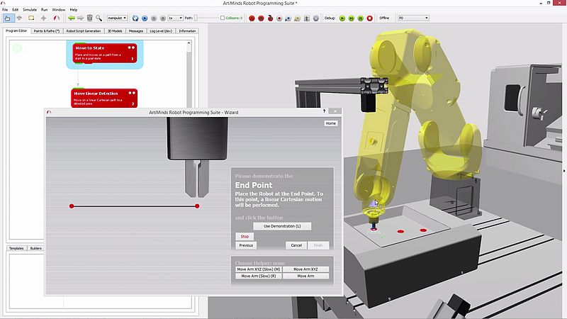
Until now, robot programming has been a task for experts. The laboratory staff lacked the necessary qualifications. How did ZF solve the problem? Wachter, "With the ArtiMinds Robot Programming Suite, we were able to provide our colleagues in the lab with predefined program modules. With the help of wizards, the lab technicians can easily configure the robot's motion sequences. This is done quickly and only basic knowledge is required."
For simple geometries, a linear movement between two points is sufficient. For more complex tasks, the robot can orient itself on the CAD model of the respective test part. The CAD2Path feature, which creates a program based on CAD data loaded into the software, helps here.
Wachter summarizes. "The simplified configuration via the Robot Programming Suite was what made this type of application in the laboratory environment possible in the first place. Even non-experts can program robots and check the result in a visual simulation."
Simulate, then realize
Simulations are one of the main tasks of the Production Tech Center Robotics anyway. For this purpose, Arnold regularly uses the Robot Programming Suite. He explains, "We are often confronted with the task of estimating whether or not a robot can meet a certain cycle time in a given situation. In simple cases, it is easy to estimate this. But in more complex projects we have to make a feasibility study.”
In the past when faced with the task of conducting such feasibility studies, ZF had to install the robot system on site at great expense, develop the appropriate application and test whether the system could meet the specified cycle time. With the Robot Programming Suite, ZF can not only program but also simulate applications, thus saving time and costs. Jonas Arnold explains, "The visualization allows us to identify potential problems in advance. This already starts with the spatial conditions. Does the available space even offer sufficient freedom of movement?"
In addition, when using collaborative robots, special standards must met in order to ensure the safety of human-robot collaboration. Arnold explains, "We must evaluate in advance, for example, where collisions between humans and robots could be possible. Can the robot arm reach head height? Are there possible clamping points? In order to ensure safety, we have to comply with force as well as pressure values and limit the speed of the robot's movements. During the gripping process, we must allow for inaccuracies that cause time delays. We can assess all of this more easily by simulating it with the Robot Programming Suite."
Jonas Arnold concludes, "For me, the greatest advantage of the RPS is the many flexible features that allow us to simulate applications even before they are actually built and also to implement new, previously non-automated tasks.”
Open for special requirements
Uwe Wachter and Jonas Arnold have already gathered several years of experience in a wide range of applications. And still, they too often encounter applications that are not so easy to implement. They find, "Airbags are sewn together in a ZF plant in Portugal. The challenge is to keep the sewing speed constant, even if the airbag does not have a uniform geometry." Realizing this task with a robot proved to be unexpectedly difficult. Because, according to Arnold, "The robot sits almost centrally from the component. This means that depending on how far and at what angle the robot arm has to move, the speed of movement would have to be adjusted continuously." The colleagues from Portugal had tried for several weeks to solve this task and finally gave up. Even with external system integrators, the requirements did not seem to be feasible.
Together with the ArtiMinds project team, ZF was finally able to work out a good solution for the implementation of the robot program. Arnold praises the cooperation and close collaboration, "We always come to ArtiMinds with special requests. There we always find open ears and helpfulness. In this way a beautiful and stable partnership has developed between us.”
Silke Glasstetter, Head of Marketing & Christopher Abel, Business Development Engineer, ArtiMinds Robotics GmbH
Automated Quality Control to Increase E-car Throughput
An application story from Creaform Deutschland
Hydraulics & Pneumatics
Today’s manufacturers of electric vehicles are facing unprecedented challenges in quality control, due to the sheer complexity of assemblies and parts, as well as shorter production times to accelerate their time to market. Automated quality control systems are increasingly becoming a key strategy to address these challenges.
Take Walter Automobiltechnik GmbH, a renowned German part and accessory supplier for big OEMs in the automotive and motorcycle industries.
An engine mount kicks off the search for an automated quality control solution
Over the past few years, skyrocketing demand from OEMs for parts to be integrated in new electric vehicles drove the company to look for an alternative inspection approach and solution to accelerate and improve its quality control. In particular, Walter Automobiltechnik wanted a solution that could replace its manual methods and traditional coordinate measurement machine for an e-car engine mount for BMW’s new fully electric Mini Cooper SE.
The e-car engine mount is a complex grid tube frame with many connection points around the periphery. Weighing 25 kg and measuring 900 x 700 x 500 mm, the mount is made of galvanized steel, which causes a reflective surface. It also features welded structural parts with complex geometries, which made them difficult and time-consuming to inspect. Because 90% of the components are not reworkable, a non-compliant mount could cause an immediate production standstill. That meant that the quality control team at Walter Automobiltechnik had to guarantee 100% measurement of the series production within a specified cycle time.
The quality control team had to spend at least 1 hour and 30 minutes to acquire measurements of each frame. Only experienced staff members were able to carry out the measurements. This inevitably caused bottlenecks at the CMM, generated lengthy computing times, and ultimately impacted the production line’s cycle time.
Creaform’s R-Series becomes the solution to improve automated quality control
Walter Automobiltechnik turned to Creaform’s R-Series of automated quality control solutions. The company implemented a custom integration of the MetraSCAN 3D-R, a powerful robot-mounted optical scanner. Located at the end of the production line, a MetraSCAN 3D-R and C-Track optical tracker were installed in two automated industrial measuring cells to increase throughput. VXelements, Creaform’s fully integrated 3D software platform, was also chosen to carry out the inspections and quality control.
Each system is configured using a 6-axis robot with a 7th axis being a rotary table. Users manually load the part in the measuring cell and, with a barcode reader, scan the required information to start the robotized data acquisition process. Once the process is complete, a report is generated, indicating if the welded parts are good or not—and what repairs need to be made.
Because of the unique feature of dynamic referencing of both the MetraSCAN 3D-R and C-Track, metrology-grade accuracy, repeatability and reliability are not compromised, even if the measuring cell is located right on the production line in the shop floor.
Walter Automobiltechnik installed the solution in less than two weeks, which kept downtime to a minimum. Staff members, including metrology experts and non-metrology technicians were trained on the MetraSCAN 3D-R and VXelements in just one day.
The results are impressive. The MetraSCAN 3D-R now generates up to 480K measurements per second, which helped the quality control team reduce its measurement times from 1 hour 30 minutes to only 8 minutes per frame—all with an accuracy of 0.05 mm. For each frame, a measurement protocol and 3D scan are stored to ensure seamless traceability.
With the solutions’ exceptional ease of use and automated data acquisition, data accuracy—even over large measuring areas—is no longer depended on operator skill. This freed up Walter Automobiltechnik’s conventional CMM for other inspections that required tighter tolerances.
According to the Walter Automobiltechnik team, the exceptional performance of their automated quality control system for the engine mount has incited them to acquire more automated quality control solutions from Creaform for other production lines. “In the future, we think this system is a must-have in the automotive industry,” said Tommy Laukdrej, Head of Quality Management at Walter Automobiltechnik.
Exploring Advancements in Electric Vehicles and Charging in 2020
An application story by Steve Hughes, managing director REO UK
Hydraulics & Pneumatics
Electric vehicles (EVs) and the wider electric transportation has gone from strength to strength in the past decade. Over the next five years, a total of eight million drivers in the UK will switch to hybrid and electric vehicles (HEVs) according to CompareTheMarket, driving demand for robust charging infrastructure. Here, Steve Hughes, managing director of transport power quality specialist REO UK, explores how the industry is shaping up for the 2020s.
EVs have proven themselves to be one of the top technological success stories of the early 21st century so far. In 2013, a mere 3,500 EVs were registered in the UK. By the close of the decade, this number had risen to approximately 255,000.
There are several factors steering this change. For automotive manufacturers, it’s becoming cheaper to manufacture EVs due to reduced component costs, substantial developments in battery technology and wider availability of large-volume manufacturing for parts such as powertrains. According to Bloomberg NEF, the accelerating rate of these changes will make EVs cheaper upfront than combustion vehicles by as soon as 2022.
Then of course there are the environmental factors, in terms of air pollution and carbon emissions. EVs are widely seen to be cleaner alternatives to conventional vehicles due to the substantial difference in carbon emissions from use, with EVs generating only 42 per cent of the carbon emissions of a conventional vehicle. Although EV manufacturing has attracted criticism from detractors for producing more carbon emissions — 15 per cent according to a report by The Union of Concerned Scientists — than their gasoline-powered counterparts, these differences disappear when EVs are in operation.
Charging: Faster but longer
The growing adoption of EVs is an undeniable win for environmentalists, but it is something of a double-edged sword for energy systems operators and electrical experts going into 2020.
EV charging points are split into three main categories: slow, fast and rapid. Slow chargers, which typically are rated up to 3 kW, are best suited for home charging as they can take 6–12 hours to fully recharge. Fast charging units are rated either 7 kW or 22 kW depending on whether they are single- or three-phase. Rapid charging, as the name implies, is the fastest. Units are generally rated 43 kW for alternating current (AC) units or 50 kW and above for direct current (DC) chargers.
Understandably, users want the fastest charging experience possible. It’s for this reason that many automotive manufacturers are investing heavily in developing faster charging infrastructure, such as Porsche’s electric pit stop that promises to suitably charge EV batteries in as little as 20 minutes.
This trend for faster charging points comes as no surprise. It’s very possible that slow charging points will largely disappear over the next few years in favour of 7 kW units. This will likely be a slow process as several EV models are only now moving to onboard chargers capable of effectively using 7 kW. Latest models of the Nissan Leaf, for example, have onboard chargers with a capacity of 6.6 kW — almost able to make full use of the 7 kW capacity of a fast point.
Grid strain
If we imagine that hundreds of thousands of electric vehicles plug in to charge at units rated between 7 and 43 kW, it becomes apparent that grid infrastructure must be robust to handle the demand.
However, it becomes more complicated when we account for the rectification that must take place to convert the AC power of many charging points to the DC required for EV batteries. This process introduces harmonic currents into the mains AC signal that, if left untreated, cause higher losses, signal interference and accelerated electrical component wear — none of which are ideal for any connected devices, let alone charging EVs.
This is arguably the biggest challenge facing the adoption of EVs and the growing usage of EV charging infrastructure, and it’s one that we explore in detail in our recent eBook R30. Unless these harmonic currents are accounted for and mitigated, the electrical grid will face a harmfully noisy electrical signal on top of sudden surges in demand.
Fortunately, electrical contractors can play a crucial role in minimising the risk by ensuring that any EV charging projects include suitable harmonic filtration components in the surrounding infrastructure. For example, installing one of REO UK’s mains line filters or harmonic filters ensures that harmful currents are attenuated and filtered out to avoid damaging the integrity of the mains power.
The inclusion of filtering components seems like a common sense solution, yet it remains one that can make a significant difference in overcoming one of the fundamental challenges in EV adoption. In fact, we believe that the consideration of such harmonic mitigation strategies at a grid level will be a key trend in EV infrastructure over the coming years.
If we are to see eight million drivers make the jump to EVs in the next five years, we must begin to reinforce our infrastructure now to cope with demand. 2020 will be in a pivotal year in ensuring charging infrastructure is up scratch to meet user expectations, both in terms of charging speed and overall system reliability.
Steve Hughes, managing director REO UK
Electric vehicles are powered by lithium-ion battery packs. Although they are used in billions of applications worldwide from cars to the latest cell phones, they are sensitive constructions. However, if care is taken during the charging process the battery life and safety can be significantly increased.
If you are thinking about buying an electric vehicle, it makes sense to consider at an early stage how this vehicle should be supplied with energy. In the vast majority of cases this will involve charging at home. That is why we want to limit ourselves to this point in this article. What do we need to look out for?
Duration of the charging process
The calculation for the loading time is done quickly. Take the battery capacity of a vehicle in kWh and divide it by the power (kW) of the charging station. This gives you the number of hours for a full charge.
The weakest link determines the pace
During the charging process always keep in mind that it consists of the mains supply, the charging station, the charging cable and the charger, just like a chain. The weakest link of such a chain always determines the maximum charging power. Thus, if the charger only has a capacity of 6.6 kW, it does not be of any help to "pump" some current into the batteries with a 22 kW charging station.
Fast charging shortens service life
Fast charging harms every lithium-ion battery. Charging and discharging lithium- ion cells can lead to lithium plating. Lithium ions are deposited on the anode surface instead of nesting between the layers of graphite. This effect leads to significant losses in performance, service life and safety. In extreme cases, lithium plating can even lead to a short circuit or since metallic lithium is highly flammable, to a fire.
Charging on 1-phase mains
The smallest available wall charging stations are connected to the 230 V/16 A household mains supply. These wall charging stations can only be used for single-phase charging up to about 3.6 kW. This is only practical in a few cases. For example, vehicles with low battery capacity for short distances or plug-in hybrids that do not rely exclusively on the electric motor.
Charging on 3-phase mains
A large number of wall charging stations for the private sector are connected to 400 V/16 A three-phase current (11 kW max. charging capacity). Practically every household offers this possibility without additional changes to the power supply system. This already reduces the charging times by a factor of 3. The simple design of these wall charging stations is particularly advantageous, as in addition to 3-phase charging, the standard on-board chargers can also be operated at 230 V (max.3.6 kW) on one phase without further fusing.
If you need more power, you have to upgrade the power supply. For example, to a stronger wall charging station with 400 V/32 A (22 kW) or 400 V/63 A (44 kW).
However, you are dependent on the help of a specialist for this. It is also imperative to clarify the technical (existing electrical load) and legal (tenants, owners) feasibility. In return, such powerful chargers offer significantly shorter charging times. Again, the performance of the built-in on-board charger determines the charging capacity that can ultimately be achieved.
Intelligent charging management
Performance is one thing. It is at least as important to use this power intelligently and safely. High-performance electronics are responsible for this. The charging management of the wall charging station communicates with the vehicle's Battery Management System (BMS). BMS are responsible for controlling and monitoring the charging and discharging process. Their main task is to ensure that each individual cell neither during charging nor discharging falls below nor exceeds a State of Charge (SoC) limit value defined for the application. The SoC value describes the remaining available capacity of a battery in relation to its nominal value.
Electromagnetic compatibility (EMC)
Today, high-performance electronics always means high-clocked circuits. And these fast circuits always carry the risk of excessive emissions of electromagnetic interference signals, which must be reduced. This problem can be overcome with EMC filters with high attenuation and a clever circuit board layout - in the 1-phase range usually even with discrete components. SCHURTER has a wide range of chassis mount filters for both 1-phase and 3-phase systems. Whether 1- or 2-stage filters are (must be) used depends on the strength of the interference signals, which should be measured in advance. For almost any interference signal and any power range, the problem of electromagnetic compatibility can be solved in a compact way.
Protect!
Last but not least – charging stations perform the lion's share of their service unattended. Generously dimensioned protection with high-quality passive components (fuses, fuseholders) helps to prevent major damage such as a fire in advance. An example of this would be the CSO high- performance clip for 10.3 x 38mm fuses. Due to the use of a special copper alloy, it is characterised by a particularly high clamping force. This results in minimal power dissipation, which is particularly essential for applications with high currents. With a typical contact resistance of ≤ 1 mΩ it is ideally suited for use in e-mobility charging stations (AC and DC).
According to Siemens, Safety is Essential for the New Normal
The social distancing solution from Siemens based on the Real-Time Locating System (RTLS) can be the solution to keep production running without putting the safety of employees in the background
Automation, Covid-19, Industry 4.0
During the corona pandemic many companies are faced with the question of how to keep their production running without putting the safety of employees at risk. One solution: the social distancing solution from Siemens based on the Real-Time Locating System (RTLS), which is explained here in an interview with Nicole Lauther, Siemens USA, who is coordinating the global roll-out of the solution.
IEN Europe: Nicole, social distancing is considered a key measure for containing COVID-19, at least in Germany. What does this mean for companies?
N. Lauther: In principle, we at Siemens are in the same situation as our customers. Either there was a complete shutdown, so that only a minimum of emergency personnel was allowed into the plants, or a plant was considered to be essential and had to continue operating. But since many countries have at least started easing their restrictions, everyone must find a way of resuming work or returning to the usual work-load – but in a safe working environment. And in this respect, according to virologists, keeping your distance is still the best measure if you don't want to wear a protective mask for an entire shift.
IEN Europe: Now, maintaining a minimum distance is not a particularly complicated rule. Why do customers ask for technical support?
N. Lauther: This is a combination of several things. On the one hand, you may simply forget the distance rule in your everyday work and stand close to other people in production, for example, in order to solve a problem on a machine. Secondly, some encounters cannot be avoided, for example in narrow aisles – this is where those in a position of responsibility need transparency to identify such points. Perhaps a company can then reposition machines, introduce one-way systems for the walkways, and so on. And finally, there is the issue of tracking in the event of an infection: with whom did an infected employee come into contact? In which areas of the plant were the potentially infected employees working that is which parts need to be disinfected? So, one is a warning function in everyday life, while the other concerns management in the case of a corona outbreak.
IEN Europe: How does the Siemens solution for social distancing work?
N. Lauther: Our solution is based on Simatic RTLS, a real-time radio locating system. Actually, it is used to optimize production processes, for example by continuously locating materials, products, and production equipment. For this purpose, a certain area is equipped with RTLS gateways, which can then locate the transponders in fractions of a second.
For social distancing, every employee now receives an RTLS tag (transponder), which has a large display and is worn visibly on the clothing like a name tag. This tag transmits the location data to a software program (SieTrace), which uses an algorithm to determine whether employees are standing too close together. This information is also shown to the employees on the display. If users do not keep their distance, the tag flashes and displays a warning. The design can be changed according to customer requirements. In addition, the positional data is stored in a database.
IEN Europe: What does it need this database for?
N. Lauther: There are two issues at stake. Firstly, is an adequate distance being maintained? Are there any parts of the plant where potentially dangerous encounters occur repeatedly? And for what length of time do the employees stand close to one another? SieTrace can display a heat map for this purpose, so that those responsible can see when and where risky situations occur and take the appropriate organizational actions to eliminate these risks.
Secondly: in the event of an infection, who was too close to which employee and for how long? Based on this information, it is possible to work out who needs to be tested for the coronavirus or even sent into quarantine – but not the entire workforce. And the software also indicates which parts of the plant need to be disinfected - but again, not the entire site. In this way, the data helps to manage a coronavirus outbreak.
IEN Europe: Coronavirus apps for smartphones are now available in many countries - for example in Germany. So why do you need an RTLS solution?
N. Lauther: There are several reasons for this. For one, reception is poor in some plants, so the smartphone apps are inaccurate or do not work properly at all. In addition, some plants prohibit the use of a smartphone, for example due to plant safety or security regulations. A third problem is the perception of an alarm. Our RTLS transponders are worn in a clearly visible way, so that not only the employees themselves, but also their co-workers in the surrounding area can hear the alarm. And then some apps (like those in Germany) are designed in such a way that the data is not collected in a database. This is fine for personal use on the street or in the supermarket - but within companies, it leads to a considerable risk and limits the options for reacting to an infection.
IEN Europe: Indoors, the apps have a considerable disadvantage: they do not recognize any structural partitions. If there is a wall between us, we can safely work at a distance of less than 2 meters - but the app might still trigger an alarm. How is it with RTLS?
N. Lauther: Locating systems such as Simatic RTLS often use "metadata", in other words, information about the structural surroundings. This enables us to clearly identify partitions and the like and to filter the alarm messages accordingly. So, problem solved!
IEN Europe: Perhaps this is a typical German question, but what do the data protection authorities have to say about your recording of data on employees' movements?
N. Lauther: This is not just a German problem, but employees in other countries are actually also worried about what happens to their data. Are people checking how long their breaks are, or which colleagues are chatting to each other? For this reason, we do not record any personal data with SIMATIC RTLS, but only a unique number (tag ID). The assignment to the individual employee, if desired, is done by the company, and in this respect an organizational regulation can be superimposed in the company. It may be specified, for example, that this assignment only be made in justified cases with cooperation between management and the works council. Each company has its own system and must also take different national regulations into account. The database is also encrypted, and access is protected. And when the system is introduced, certain areas such as changing rooms or toilets can be excluded altogether.
Ultimately, those responsible in the companies must get together and decide how to balance the safety requirements on the one hand and the personal rights of the employees on the other. And then it must be clear: dispensing with technical aids completely does not solve the problem!
IEN Europe: Now, if I, as a customer, am enthusiastic about your solution because it helps me to get my production running again, how quickly can I install Social Distancing and Simatic RTLS?
N. Lauther: The important thing here is that we are talking about existing technologies. The system can be operated in standalone mode, so that no major effort is necessary for integration. In this respect, the system can be introduced at very short notice – currently we already have several test installations in the USA.
IEN Europe: Can I also integrate the app in my control center software?
N. Lauther: Yes, of course; we offer this as a service to our customers.
IEN Europe: And what about my investment if a vaccine or medicine becomes available?
N. Lauther: The great advantage of an RTLS-based solution is that the tracking can be used like an infrastructure for a variety of applications. And RTLS also offers great advantages for the actual production management, which are reflected in a swift return-on-investment (RoI). Installing Simatic RTLS thus kills two birds with one stone: customers can introduce a solution to the coronavirus problem at very short notice while at the same time investing in the future viability of their operations to develop strong competitive advantages in both the medium and long term.
Edge Computing Holds the Key to IT/OT Integration
An application story from Christian Nomine, Strategic Product Manager Visualisation, Mitsubishi Electric Europe B.V.
Electronics & Electricity, Industry 4.0
The digital transformation of industry has given new momentum to the connection of the operational technology of the plant floor to the information technology of the higher-level enterprise. However, making the most of the potential of digitalisation requires more than just a network connection between these two levels of the business.
Christian Nomine, Strategic Product Manager Visualisation, Mitsubishi Electric Europe B.V. explains how Edge computing provides an essential middle layer between the two, giving manufacturers the tools, they need for the smart connection of their business processes.
The goal of the digital transformation is to provide a foundation to boost productivity, increase product quality, optimise asset availability and maximise plant utilisation, to better meet the real-time demand requirements of customers. That foundation is built on a rapidly growing network of increasingly sophisticated plant floor devices – the so-called Industrial Internet of Things (IIoT) – all generating data related to different aspects of a plant’s operations.
But surely data is data. Why should a direct vertical link between the shop floor and the higher-level business systems not be a sufficient enabler to realise the goal of the digital transformation described above? The answer lies in the way in which information technology (IT) and operational technology (OT) platforms have evolved to deal with different types of data with different processing requirements. The OT world now operates in real-time with process speeds of seconds or below; the IT world in contrast operates at much greater sampling times, from minutes to hours or longer.
Behind the model of Industry 4.0 is the need for the OT and IT spaces to each capitalise on the data the other can provide. But neither is set up to translate and interpret the data received from the other in a fashion or timescale that can have a direct impact on the plant floor operations in real time. As the digital transformation progresses, the result of direct IT/OT integration is often simply one delivering high volumes of unfiltered data instead of just the relevant information that is needed to drive genuine improvements in operations.
Some have argued perhaps the Cloud could provide an environment for managing these high volumes of data, providing a platform for efficient data aggregation, filtering and analysis. And certainly, protocols like OPC UA can provide a direct link from the shop floor, through the higher-level systems and on to the Cloud. But while the Cloud provides an ideal platform to develop knowledge about the plant operations, it is not the right platform to turn knowledge into action for the production operations. Yes, it can provide useful and essential data analytics functions, but not the real-time aggregation and analytics that are needed at the OT/IT bridge.
Bridging the divide
A more appropriate solution for OT/IT integration is provided by the new smart technology that is appearing at the ‘Edge’. Forming an intermediate layer between the shop floor and the higher-level business systems, these Edge computing technologies provide a simple interface between the IT and OT worlds, as well as new options for where data analysis takes place.
Mitsubishi Electric’s MELIPC Edge-Computing solution offers this functionality combined with OPC UA compatibility. Data can be pre-processed locally and aggregated to create valuable information for the systems that need it. And it can seamlessly connect the shop floor with higher level IT systems such as MES and ERP platforms.
By performing sophisticated data analysis in real-time, increasingly making use of AI algorithms as well as machine learning to deal more intelligently with data, the MELIPC is able to make improved production efficiencies a reality. The cost of data processing can also be considerably reduced, as only the information that is necessary and relevant is passed from one level of the enterprise to the other.
The MELIPC provides a real time data logging and processing environment in a ruggedized industrial form factor. From a data processing perspective, it incorporates a suite of analytical tools including multiple regression analysis, the Mahalanobis-Taguchi system and Statistical Process Control (SPC) as well as AI functionality such as Similar Waveform recognition – giving feedback to the plant floor in real time.
As a result, it can combine functions from data collection, filtering, processing and analysis utilising shop floor knowhow with diagnosis and predictive maintenance feedback. This occurs within a real-time information flow that can drive the production systems’ decisions. It delivers a foundation for the digital transformation of the business, providing a platform for connecting machines and devices so that manufacturing processes can react more quickly and more intelligently to production changes, whether they be asset-centric, demand-led or supply-driven.
The rising volumes of data from the plant floor, and the requirement to use that data more intelligently is both an enabler for the digital transformation of industry and a challenge. Edge computing as an intermediate layer between IT and OT is the answer to that challenge, paving the way for the event-driven architecture that defines Industry 4.0. It is the key enabler for any manufacturing plant to realise the potential of transforming into a smart operation. This technology provides the natural bridge between the worlds of OT and IT in a format that both sides of the divide can embrace.
Mobile Access to Production Data: Custom OPC UA Apps for FDT 3.0 Applications
Next Gen FDT/OPC UA IIoT Ecosystem Assists Developers
Industry 4.0
Nowadays, industrial organizations must find ways to effectively manage field devices and reduce overall operating and maintenance costs. They need to monitor the status of critical assets, view equipment health analytics on real-time dashboards, and automate actions based on predictive insights. Experience has shown that easily customized applications help in connecting, informing and empowering the industrial workforce so they can make better decisions every day.
Automation industry stakeholders can utilize a variety of third-party software developer toolkits and apply the power of the OPC Unified Architecture (UA) to create bespoke Apps leveraging all the data available in the FDT® 3.0 IIoT Server (FITS™) application.
Collaborative Evolution Advances Digital Transformation
Since 2014, the FDT Group and OPC Foundation have worked together to provide greater access to critical information throughout the industrial enterprise. The FDT standard is the hub of real-time information from tens of millions of Device Type Manager™ (FDT/DTM™)-enabled devices installed in the field, while the OPC UA standard provides an infrastructure to make this information available to thousands of enterprise applications and platforms.
OPC UA is the required vehicle for merging Information Technology (IT) and Operational Technology (OT) assets within current automation architectures. The protocol unites these two sectors and integrates them within a comprehensive information model. In addition, OPC UA is highly efficient and secure, allowing encrypted transmission and authenticated and authorized data access.
FDT technology was originally developed to unify the OT world of disparate networks and devices from different vendors and has become recognized as the de-facto industry standard for industrial device integration. Now, with the updated FDT 3.0 standard, it employs an FDT Server natively integrated with an OPC UA Server to provide centralized OT and device data to the IT world. No additional work is needed on the vendor, device, system, or end user sides, since OPC UA is auto-enabled within the FDT IIoT Ecosystem of FDT Servers and DTMs. All authorized OPC UA Clients have access to operational data, and this information can be customized as necessary without requiring OT personnel to assume the unwanted role of the middleman.
Another strength of the FDT approach is that it takes care of the different networks in the automation architecture and presents a common model for field devices. Otherwise, the user is required to access the Programmable Logic Controller (PLC) or Distributed Control System (DCS) to gather network and device information and map tags to OPC UA. With the FDT 3.0 solution, the FDT Server sits at a peer level to the PLC or DCS and has direct access to all installed devices without the need for intervention or changes to the control environment.
In general, the flexibility of this architecture achieved through harmonization of data in the built-in FDT 3.0 OPC UA Information Model allows access to all devices from different vendors using a variety of bus protocols and networks to communicate across the entire network hierarchy. The FDT Server provides the OPC UA interface that enables secure data transport over the corporate Intranet or the Internet through an encrypted connection between the server, clients and mobile devices, including Apps.
Next Gen FDT/OPC UA IIoT Ecosystem Assists Developers
The newly launched FDT 3.0/OPC UA IIoT Ecosystem, consisting of an FDT Server and DTMs, delivers universal device integration and a data-centric platform to mobilize the industrial workforce with modern and diverse deployment options, including cloud, enterprise, edge, on premise, and single-user desktop environments.
Within the FITS architecture, the platform-independent FDT Server serves as the pivotal IIoT hub empowering the intelligent enterprise. It is built on top of application business logic that manages all device DTM instances. The FDT Server includes a web services portal allowing access from authenticated mobile devices or any major browser, along with an OPC UA interface for IT/OT convergence and enterprise access in the process, hybrid and discrete automation sectors.
A key feature of the new FDT 3.0 standard is that all FDT Servers and DTMs automatically provide full OPC UA support without additional effort or coding. This means any authorized OPC UA client can browse the project structure in the FDT Server to locate device-specific, real-time information. There is easy integration of live plant floor data into Apps, dashboards and manufacturing execution systems without the need to touch the DCS or PLC configuration. Users have free and easy access to this information through a built-in and fully “wired” OPC UA Server within the FDT Server Common Components developer toolkit. The same holds true for DTM Common Components, as OPC UA is auto-enabled for DTMs. No additional coding or work is needed in either case.
As part of the FDT 3.0 solution, standard integration of information provided by DTMs into the FDT/OPC UA Information Model optimizes advanced device diagnostics, configuration and remote asset management. This information model enhances the management of networks and devices, helping to optimize the enterprise by giving access to data without the need for protocol-specific handling, providing support for a wide range of devices.
Innovative OPC UA Apps Add Flexibility to Device Data
Third-party developers have begun to develop toolkits to write Apps that can help the IT and OT workforces’ function more effectively by having device-specific, real-time data available at their fingertips on mobile devices. OPC UA’s robust capabilities can be used to build a wide range of custom Apps leveraging the new FDT 3.0 IIoT Server solution.
Thanks to the versatility of the FDT 3.0 architecture, anyone can create customized Apps to meet their needs based off the available diagnostic data—whether it is a customized Key Performance Indicator (KPI) dashboard or an App tailored to a specific family of devices. These Apps offer a new model for providing a customized view of production data via the flexibility of the FDT 3.0 architecture.
Due to implementation of the OPC UA companion specification for FDT, FDT 3.0 applications can access device DTM interface data via any authorized OPC UA Client. This allows the DTMs to be integrated in applications in which OPC UA is used for data exchange or for executing device-specific functions.
Both automation suppliers and end users can develop customized Apps to access device data in the FDT 3.0 Server environment. Third-party toolkits, available for a wide variety of platforms (iOS, Android and Microsoft) and languages, save developer teams from having to become experts on the OPC UA architecture and eliminate the laborious steps necessary to create an OPC UA Client. Rather, developers can focus on customization aspects including acquiring and presenting their data.
The development of custom Apps covers a broad spectrum of use cases in the areas of production operations, asset monitoring and equipment maintenance, among others. For example, with the FDT Server solution integrated with a native OPC UA Server, a remote asset monitoring application can be created to monitor the health of a field device on a different network and to alert technicians if there are abnormal conditions requiring immediate attention. Developers can also create performance dashboard Apps for manufacturing facilities, which employ OPC UA to obtain relevant OT and production data. On the IT side, the availability of real-time data from OT systems allows for the creation of custom reports based on KPIs to help management better evaluate operational productivity, standards compliance, etc.
Robust Communication Model Enables Real-time Data Access
Thanks to the FDT/OPC UA Information Model, users have access to real-time data to make better real-time decisions. All that data is now harmonized within the information model and presented in a logical, defined and uniform manner. Even device-specific information is provided in a standardized way while still customizable based on individual application requirements. The look-up of information is the same for users of all clients, even though the devices may be significantly different. The FITS architecture benefits from both a Client-Server and PubSub communication model approach. Users have the flexibility to choose the method that best fits their needs.
Client-Server
The FDT 3.0 OPC UA Server supports a Client-Server-based request-response communication mechanism between the OPC UA Client and generic client applications. This approach makes the full range of information model access available via services and, in doing so, follows the design paradigm of Service-Oriented Architecture (SOA), in which a service provider receives requests, processes them and sends the results back with the response.
Publish-Subscribe (PubSub)
Going forward, the Publish-Subscribe (PubSub) communication model will provide an alternative mechanism for data and event notification with FDT 3.0. While in Client-Server communication each notification is for a single client with guaranteed delivery, PubSub has been optimized for on change-only, one-to-many configuration. The PubSub approach is essential for secure multicasting, one-to-many publishing, machine-to-machine communication, dynamic network relations, and a number of additional scenarios.
Enabling the FDT OPC UA Server with OPC PubSub communication will significantly reduce communication traffic between asset health monitoring applications and the server application, thus improving performance and making the solution scalable to IIoT requirements. Remote monitoring applications will be able to monitor asset health on a different network in real-time, using bridging protocols like AMQP and MQTT.
Flexible Architecture Benefits the Automation Community
From a broad perspective, the global automation community will benefit from the flexibility of the new FDT 3.0 (FITS) architecture, which supports production data customization for the IT and OT worlds within industrial manufacturing—even though these domains have different interests and requirements. The FITS solution optimizes the connection of diverse automation systems and devices, delivers complete interoperability across both current and emerging standards, and supports the convergence of the business information and plant operating technologies. Best of all, the enhanced FDT 3.0 architecture is scalable to suit the needs of a single manufacturing facility or an entire industrial enterprise.
Both automation suppliers and end users can take advantage of ongoing FDT technology advancements to write customized Apps that leverage the rich data available in the FDT 3.0 OPC UA Server. All the toolkits, information and demos required for App development and testing purposes are openly available to interested stakeholders at https://opcfoundation.org/products.
For automation vendors, the FDT 3.0 solution establishes an architecture making it easy to provide a DTM that can be used for integration with service tools as well as creation of a digital twin with accurate information about the supplier’s device.
By establishing a single point of access for device data, the FDT IIoT Ecosystem provides a comprehensive and consistent source of information for different service and operation use cases within plant or factory production systems.
Conclusion
FDT Group’s FDT 3.0 (FITS) architecture will empower the intelligent enterprise by providing native integration of the OPC UA standard and a single device data interface with mobile access cloud-to-plant-floor. This robust technology will benefit the automation community by simplifying compliant development of customized, FDT- and OPC UA-based Apps for a wide range of business decisions, industrial operations and maintenance tasks.
5 Reasons Manufacturing Businesses Should Accelerate Adoption of IIoT
An application story from Futurism Technologies
Industry 4.0
Futurism Technologies. What if a manufacturing business could leverage advanced analytics to forecast events pertaining to equipment breakdowns before they actually happen, use real-time and actionable insights to drive production and manage inventory, and help decision makers take right decisions at the right time? Industrial Internet of Things aka IIoT is driving such capabilities facilitating unmatched operational efficiencies and production performance like never before for the manufacturing sector.
Good news is that manufacturing businesses across the world are embracing the idea of IIoT and the growing need to embrace it. In addition, with the mounting challenges of digital disruption and the pressure to keep up with global competition, more number of manufacturers are turning to IIoT as the keystone of their digital transformation (DX) initiatives.
Did you know?
Manufacturing industry is expected to be the largest sector for Industrial IoT platforms as more and more companies realize the pros of connecting industrial equipment and machinery to streamline their operations and tame costs.
Since we are the cusp of the Fourth Industrial Revolution wave aka Industry 4.0, wherein businesses are realigning their digital investments and priorities, organizations ought to speed up with their digital transformation plans.
This is the reason digitization has become a top priority for manufacturing businesses worldwide to survive and thrive in a post-pandemic and competitive world. And what better way to kickstart your digital transformation journey than IIoT to creating a smart factory or connected factory.
Here are top five reasons manufacturing businesses need to embrace IIoT to stay ahead of the curve:
1. Mobility
IIoT mobile solutions help a manufacturing organization to improve its production efficiency and maintenance activities, as a part of its Industry 4.0 digital transition strategy. IIoT mobile solutions are aimed at mobile workforce within the production and maintenance sphere. With IIoT, you will always have access to work orders from anywhere in the plant or unit and be able to manage or track spare parts from the warehouse or from the shop floor. Mobility within manufacturing and asset management helps to create workforce flexibility and facilitates tactical abilities for addressing issues pertaining to efficiency, productivity, etc. Further, uninterrupted and on-demand access to system information leads to improved efficiency.
Key benefits include:
• Timely alerts to the engineering team/department directly via smartphones or wearables (smartwatches) when critical events occur in production line, supply chain, logistics, inventory, etc.
• Assisting field service experts/technicians on the run
• Ability to perform routine maintenance and material management activities on the go
• Quick and easy access to documentation
• Easy and quick access to SOPs, technical documentation, work instructions, etc. as and when needed.
2. Remote monitoring
IIoT empowers a manufacturing business to supervise, diagnose as well as solve issues for connected machineries and equipment remotely. Manufacturing businesses are utilizing IoT assets to connect systems and machines together, which is a paradigm shift enabling real-time asset monitoring capabilities. Connected assets offer the opportunity to monitor them for reliability, performance, safety and compliance in real-time and on the go. Asset monitoring is a boon in remote manufacturing businesses where sensors help to track production operations and send status/alerts or reports to the right personnel. It also provides a platform to control and manage assets for improved operation and production facilitating timely and proactive manufacturing decisions.
Connected machines and equipment can be easily diagnosed to check and identify potential issues. Remote monitoring includes tracking anything from usage and performance of a machinery/equipment to capturing alerts, tracking performance history, etc. Simply put, technicians can perform preliminary diagnostics from a remote location and recommend corrective measures. Efficient asset tracking in manufacturing leads to seamless status monitoring of key machineries and equipment as well as final products, to prevent quality issues and improve supply chain operations.
3. Aftersales
As IIoT enables a manufacturing business to diagnose and monitor connected equipment remotely, it is of great help when it comes to aftersales.
For an equipment manufacturer, aftersales means profit and revenue. This is where most of the manufacturing businesses fail, as they heavily rely on old school aftersales delivery models, which are not only inefficient, but are also costly.
In a traditional old-school aftersales delivery model, service technicians are required to hop between multiple site locations i.e. from the installation site to the manufacturing units and the other way around. On the other hand, connected equipment not only drives efficiency, but also eases the aftersales service model. Yes, the technicians can simply diagnose issues remotely and can then reach the installation location or site armed with the required tools to repair the same. This is how IIoT is speeding up the service delivery for a huge number of equipment manufacturers across the world.
4. Predictive Maintenance
According to the US Department of Energy, having a reliable predictive maintenance model in place can help a manufacturing business achieve 70% reduction in breakdowns, tenfold increase in ROI, 25%-30% reduction in maintenance costs and 35%-45% reduction in downtime.
For any manufacturing business, unplanned downtime can cost hundreds and thousands of dollars per hour. If the machinery breaks down unexpectedly, the manufacturing organization incurs a plethora of costs related to recovery and repair. In addition, there are costs pertaining to the disruption in production and supply chain. Having a predictive maintenance model in place can save the day here. According to a study by Accenture, IIoT could help cut equipment breakdowns by up to 70%.
IIoT can help technicians and experts perform proactive analysis for predictive intelligence. For example, if an equipment monitors a temperature range that is exceeding the required maximum limit, an alarm would go off. Now in a traditional setting, an operator would respond to such an alarm. Nevertheless, intelligent analytics derived through predictive maintenance model in an IIoT network would make it easy to foresee and prevent such events well ahead of time. Since unscheduled downtime consumes a good amount of a manufacturing organization’s production costs as well as time, having a predictive maintenance model becomes evident.
5. Connected Intelligence
By connecting equipment and machines, manufacturing businesses create an intelligent network of connected devices that coordinate and communicate with each other autonomously with little human intervention. With such use cases, businesses can collect as well as contextualize data coming from remote manufacturing equipment/assets and systems into intelligent and actionable applications. This helps to provide proactive insights into KPIs thus, helping in faster diagnosis. In addition, manufacturers can now choose to connect to different data centers and unify them all to facilitate real-time data visibility across diverse manufacturing systems and units.
IIoT enabled equipment thus facilitates connected intelligence, which transmits actionable and real-time insights to all the manufacturing stakeholders allowing them to manage units and assets efficiently on the run from anywhere.
Cyber Security
By 2025, the number of connected devices and equipment is expected to surpass 25 billion. From smart factories to smart cities and smart homes to smart workplaces, IoT is reinventing the way we live and perform daily business. This is why manufacturing businesses cannot afford to ignore IoT security. Yes, security ought to be a top priority when it comes to a connected or smart factory.
Mobile devices, connected equipment, sensors, devices, etc. increase the need for cybersecurity. A smart factory powered by IIoT demands for better and round the clock visibility, security and control over all its endpoints including the sensors, applications, mobile devices, IoT devices, wearables, etc.
Takeaway
IIoT has the ability to reimagine a manufacturing business as we see it today. As evolving industry dynamics and cutthroat global competition continue to push manufacturing businesses to reimagine their operations, data-driven and smart manufacturing models powered by the Industrial Internet of Things becomes quintessential.
Last but not the least, for a manufacturing organization to win at IIoT, it is advisable to kick off its digital transition plan with a phased roadmap with smaller projects and goals before building on a comprehensive IIoT network. This would help in optimum ROI and long-term success. Fact is that, more data will be created from connected equipment and systems and thus, the scope of actionable insights a manufacturing business can derive from IIoT is limitless.
Trends in e-mobility within the European Automotive Industry to Look out for
An application story from Omron
Industry 4.0
New approaches, such as AI and integrated robotics, could reshape future production processes. Seven tips for automotive companies.
At the beginning of 2020, very few business leaders would have predicted the huge challenges that would hit companies over the next few months. With the disruption caused by Covid-19, the EU Commission now estimates that economic output in the Eurozone could crumple by 8.7 percent this year.
The automotive industry has been particularly affected, with the virus exacerbating the decline in sales. For example, the Center for Automotive Research (CAR) at the University of Duisburg-Essen forecasts that German vehicle manufacturers and suppliers could lose a quarter of their total workforce by 2030. A similarly gloomy picture is also emerging in the UK. In contrast, automotive supplier AMZ predicts that the growing demand for electric cars could lead to the creation of many new jobs.
The challenges facing manufacturers and suppliers mean that they will need to develop new strategies in order to future-proof their production and processes. These will increasingly include items such as innovative technologies, robotics, sensors, artificial intelligence (AI) and integrated solutions. Industry experts believe that the move from traditional car production to electro-mobility (e-mobility) is now much more feasible and will boost both the efficiency and sustainability of production processes.
European companies risk being left behind
In addition to declining sales and stringent regulations, the biggest challenges facing the European automotive industry include strong competition from Asia, along with pressure to provide innovation and sustainability. Many European providers are finding it hard to keep up with companies in China, Japan and South Korea.
Henry Claussnitzer, Business Engagement Manager Automotive at Omron Europe, comments: “There’s also the question of whether the industry depends too much on technologies such as batteries. One thing is certain: to be competitive, companies must reposition themselves as quickly as possible. Innovative and integrated strategies are essential. These will include robotics, high-performance sensor and control technologies; and also intralogistics, AI and machine learning.”
The need for a common vision
Alfred Pammer, Head of Factory Automation at cts GmbH, an Omron partner and system integrator, points out the many different national and international regulations with which automotive companies have to comply. “Sustainable production is becoming increasingly important,” he says. “At the same time, the industry mustn’t become over-regulated. A uniform international approach would make sense, as different country laws slow down processes and innovations and sometimes even block them. There’s a lot of catching up to do.”
The strict European data protection guidelines are a good example of the challenges faced by the industry. Alfred Pammer continues: “As artificial intelligence thrives on data analysis, for example, a better balance should be created here so that Asian markets don’t move ahead while European suppliers are increasingly left behind.” At the same time, it’s vital to constantly strengthen customers’ trust in a company’s brand and products. “Without a strong integration and technology partner,” he says, “the transformation from a traditional automobile manufacturer to a high-flexibility, low-volume e-mobility company won’t be feasible.”
Examples of transformative technology
Another topic that will become increasingly important to companies in the automotive sector is data analysis. Many new technologies, such as AI and the Internet of Things (IoT), require integrated and well-thought-out data strategies. One example is Predictive Maintenance: the maintenance of machines based on information collected at the machine level (‘at the edge’). Powerful software solutions are the key to ensuring connectivity and communication between the systems. Such technology also makes the transition to the factory of the future easier. For example, production lines can be ‘smartly’ connected to mobile robots, driverless transport systems (also known as automated guided vehicles or AGVs), cobots, ERP, MES etc.
A case in point is BMW. For greater flexibility and links between work processes, the company uses innovative transport and logistics concepts. These include mobile LD robots from Omron for transporting materials for production. These autonomous intelligent vehicles (AIVs) are equipped with a conveyor attachment developed by cts. The system integrator has developed a complete technology package, specifically tailored to BMW's requirements. It consists of the LD robots and conveyor attachments, plus software that connects the Enterprise Manager with the company's own ERP system. Similarly, Continental relies on AIVs made by cts. “The heart of Industry 4.0 is software, which brings everything together,” explains Alfred Pammer.
Jorge Pereira Hernández, General Manager of Keyland Sistemas de Gestión, also points out the growing importance to the e-mobility industry of smart robotics, including collaborative robots (cobots), interacting with other technologies. This approach will not only support efficiency and sustainability but will also offer a particularly quick return on investment (RoI). He says: “At the same time, companies benefit from standardised, optimised processes. The many different vehicle drive concepts require automated workflows and controls, as well as intelligent systems that support human employees and minimise errors. Automotive companies need to take action now.”
Conclusion
Henry Claussnitzer sums up that the use of robotics, AI, and sensor, image and vision technology in the factory of the future should always be viewed as a holistic overall structure: “A data-based approach will help European companies to act more cost-effectively and more competitively. Battery manufacturing is a good example, because it requires highly integrated systems and processes. An intelligent warehouse system flanked by mobile robots can significantly increase process efficiency while reducing manual effort as well as errors and waste.”
Demand-based Control Increases Efficiency in E-mobility
Provides software solutions applications in the field of electrification of auxiliary equipment
Electronics & Electricity, Industry 4.0
Not only electric traction drives, but also the numerous electrically operated auxiliary units in electrified commercial vehicles and mobile machinery are becoming increasingly important. Efficient system solutions guarantee greater range and lower operating costs. The compact, modular and scalable T6 inverter system from KEB Automation provides for example buses with a demand-oriented electric drive for the air compressor and power steering pump.
Integrated DC filter technology as standard
The intelligent control system belonging to the T6 system offers numerous software solutions for almost every application in the field of electrification of auxiliary equipment. This means that nothing stands in the way of flexible expansion of the T6 system with a further drive module, for example for an innovative CO2 heat pump. The T6 is equipped with integrated DC filter technology as standard. This feature ensures unique electromagnetic compatibility in the system network and thus makes an important contribution to operational safety.
The World from the Perspective of an Infrared Camera
An Automation Technology's Application Story
Vision & Identification
Maybe I should introduce myself first: My name is IRSX-I, I am an infrared camera and belong to the IRS family of AT - Automation Technology. IRSX-I sounds pretty wacky at first, I know, but my creators wanted to emphasize my ability for outstanding technology. Because I am quite a valuable package. Not in the material sense, but in terms of my smart and autonomous functionality. Since I am so small and compact, no one would expect that from me, but I give you my word for that. I am a so-called all-in-one solution and you can let my work anywhere on my own. And because I can be used so autonomously and also communicate independently with the one that is connected with me, I am worldwide unique. So you could almost think that the expression "small but powerful" was invented just for me.
All-in-One-Solution for thermal process monitoring in industry
I will also explain why. My view of the world is quite different from yours. I am literally in completely different spheres. While you can capture the visible light spectrum with your eyes, my visual world is in the infrared range, i.e. in the range of heat radiation. Take the mobile fever control "FebriScan" from my employer AT - Automation Technology as an example. Thanks to my special skills, I can see exactly which area of your face is the warmest - and these are the inner corners of your eyes. Here, in cooperation with my friend, the Blackbody IRS Calilux, who verifies my measurement, I can measure your body temperature with an accuracy of +/- 0.3 degrees. Especially now in Corona times this is of course a huge advantage, because I am able to do great things although being such a small device by giving you a signal if your body temperature is too high.
And speaking of living beings, did you know that I once made a trip to the Arctic Circle? I am a real globetrotter when it comes to discovering new adventures. Anyway, there I took up the trail for whales to ensure the protection of the animals around the research vessel Polarstern. However, this mission required quite detailed preparation, as we had temperatures of up to -50 degrees Celsius in these regions. Accordingly, a new robe was made for me and my functions were optimally trained with a specially developed software so that I and my seven companions, who had also been hired for the job, could pursue whale watching without being disturbed. For this job, we got the pole position around the railing of Polarstern, so that every time we detected the blow of an animal within a radius of two kilometers, we could alert the researchers. Now you're probably asking yourself why we focused on the whale's fountain in particular, right? Well, the water that the whale ejects is blown out breathing air after its dive and has a higher temperature than the air at the Arctic Circle. Since we are focused on heat radiation, this blow was more visible via infrared.
Smart technology provides AT infrared camera with monopoly position
Finally, I would like to tell you about my spectacular assignment at NASA and at Elon Musk's company SpaceX. You don't make trips like that every day. As you can probably imagine, the material for spaceships must be one hundred percent free of defects to avoid unnecessary risks. That's why I got an exclusive look behind the scenes at both NASA and SpaceX - in the most literal sense of the word. With my ability to use active thermography, I am able to detect defects below the surface that are invisible to the human eye. By the way, this working process is called non-destructive testing and requires high-precision measurements. Therefore I was double motivated and took a meticulous look at every detail, no matter how small. It was really a lot of work, but in the end it was worth it.
As you can see from these examples, as a member of the infrared association I am a competent and indeed unique all-rounder. I can work around the clock in any industrial sector and help people to do their job better and faster. At the same time I am quite undemanding. You just have to give me a cable or the password of a WLAN access and I start reliably. Sounds like a perfect colleague, doesn't it? If you need someone like me, then please contact my boss or the sales colleagues. They know exactly where you can best and most effectively use me to optimize your processes.
BMW Chooses Inspekto to Bring AI to the Factory Floor
The BMW plant in Steyr, Austria, is the BMW Group’s largest engine plant worldwide. At the facility, the top priorities are quality, efficiency and the transformation to Industry 4.0 through the implementation of digital technologies at shop floor level. To improve all three, plant managers embraced Autonomous Machine Vision, a new technology for quality inspection developed by German-Israeli company...
Artificial Intelligence, Vision & Identification
The BMW plant in Steyr, Austria, is the BMW Group’s largest engine plant worldwide. At the facility, the top priorities are quality, efficiency and the transformation to Industry 4.0 through the implementation of digital technologies at shop floor level. To improve all three, plant managers embraced Autonomous Machine Vision, a new technology for quality inspection developed by German-Israeli company Inspekto.
In line with BMW’s mission to improve production processes using digitalisation, the Steyr plant has several state-of-the-art machine vision solutions in place to inspect the quality of its engines.
However, even the most sophisticated traditional machine vision solutions suffer from pseudo-errors, where the solution indicates the presence of a defect in components that were actually made to specification. This creates an extra and unnecessary loop in production, since flagged items need be conveyed to a repair station, where an employee rechecks them manually.
“The most problematic issue is that with increasing pseudo-defect rates, employees at the repair station could let their guard down and assume that an actually defected item is good,” explained David Bricher, PhD candidate and expert in innovation and digitalisation at BMW. “BMW is not willing to compromise on quality and we want to prevent this scenario at all costs.”
Democratising quality
BMW is a strong believer in bringing AI-based technologies to the shop floor, so plant managers were on the lookout for an intuitive quality assurance technology. “The BMW Start-Up Garage helps us find new companies with ground-breaking ideas to improve our processes,” said Bricher. “The team researched several companies with innovative machine vision solutions, but only Inspekto offered exactly what we were looking for — a system that is out-of-the-box, and so intuitive that any employee can set it up.”
Inspekto then introduced BMW to the world’s first Autonomous Machine Vision system, the INSPEKTO S70.
“As opposed to traditional solutions, made up of several components that are selected and assembled by a systems integrator on a project base, the INSPEKTO S70 is a self-contained product,” explained Harel Boren, CEO and co-founder of Inspekto. “This eliminates the lengthy and complex integration phases that characterise traditional machine vision projects and puts the potential of industrial inspection right where it belongs: in the hands of the QA manager.”
Convinced by the capabilities of the INSPEKTO S70, BMW Group Plant Steyr purchased four systems and started a pilot phase to check their suitability for complex applications. Following its success, the systems are now already used in two different use cases — a connector with many small, hardly visible components and a fuel pipe. In both cases, the plant has noticed an improvement in quality and a noticeable reduction of false detection instances.
The Plug & Inspect® experience
“For me, one of the most interesting characteristics of the INSPEKTO S70 is its ease of installation,” confirmed Bricher. “At BMW, one of our main targets is to bring the potential of AI closer to the production field. We want to make AI easy to understand so that it can really serve our people. We have to get rid of the mystique that surrounds the technology — people have to be able to say: I work with AI.”
This philosophy perfectly mirrors Inspekto’s mission to democratise machine vision by putting a vision inspection product directly into the hands of the people on the shop floor. Thanks to the patented Plug & Inspect® technology that powers the INSPEKTO S70, the user simply switches on the controller and ensures that the field of view (FOV) covers the location to be inspected. The user then presents an average of 20 to 30 good items to the system, which will automatically learn their characteristics.
Much like a human being, the INSPEKTO S70 knows when it has enough information about a product and informs the user that inspection can start. Anything that is different from the characteristics of a good part, that the system has ‘memorised’, will be flagged as an anomaly. “Typically, machine vision solutions require a long training process, during which they are exposed to hundreds of defective parts. But in a manufacturing environment dedicated to the highest levels of quality, we don’t have that many defective parts readily available, so we would have to produce them explicitly for training purposes,” explains Bricher. “The INSPEKTO S70 only needs good parts, which is a huge advantage. We produce good parts all the time!”
The more the merrier
The BMW Group Plant Steyr needs to inspect many different kinds of engines and parts, often on the same production line, so traditional machine vision solutions are limiting because they are developed ad hoc to inspect only one item. The INSPEKTO S70, on the contrary, can inspect an array of different products on the same production line and easily switch from one to the other, providing maximum flexibility.
The benefits of Autonomous Machine Vision are already visible at BMW Steyr. “The most important thing for us it to ship perfect engines. In this sense, the INSPEKTO S70 has already proved to be a valuable tool,” added Bricher. “The other priority is efficiency. By eliminating pseudo-defects, the system allows us to avoid the extra loop of manual double-checks.
“This also means that we will reduce costs in the long run, because employees will not waste their time rechecking components, they can instead be assigned to more productive tasks. But the more important thing for me is that with the INSPEKTO S70 we have brought AI closer to our production employees.”
Analog Devices Presented New AI-driven Platform at electronica 2020
Presented at electronica 2020, this AI-driven scalable platform collects data and gives feedback for better fault identification
Artificial Intelligence
ADI OtoSense aims to accelerate the digital journey of every companies of any size. OtoSense is an AI-driven, scalable platform enabling energy efficient Condition-based Monitoring (CbM). It solves two major concerns: Real-time edge interpretation and AI for sensing interpretation, which uses human expertise to help ADI software platform learn and progressively become an expert itself.
This platform detects and interprets in real-time any sound, vibration, pressure, current, or temperature for continuous, condition-based monitoring and on-demand diagnostics. It detects anomalies and learns from interaction with domain experts while creating a digital fingerprint to help identify faults in a machine. It can for example predict breakdowns which may cause costly downtime, damage, or catastrophic failure.
From experts’ specific knowledge to a general agnostic approach
OtoSense creates different ways of interaction between human and machines. It has the capability to make sense of data by digitizing the human expertise and bringing it towards the customer’s environment. Nicolas Layus, Director of ADI OtoSense Business Unit explained on how ADI noticed the need for such a tool: “We can see that numerous markets are moving to the digital transformation. Two factors are accelerating the demand for digital solutions: people who have been working for 20+ years and gathered all the knowledge and expertise on specific assets are retiring. As soon as they retire, unless the knowledge has been captured in a meaningful way such as leveraging a platform like ADI OtoSense where the user can digitize it, that knowledge would be lost. At the same time, technology enhancements like Industry 4.0 or 5G have enabled the capability to collect much more data, to know what is normal from what is abnormal.”
OtoSense is not engineered for specific markets or specific assets. It is an agnostic tool with a “bottom-up” approach. This means that the focus is on the demand from industry customers. Nicolas Layus continued: “The second reality is that when you notice an issue, you shall ask your provider to fix a specific problem, and another provider to fix another specific problem. Nowadays a lot of start-ups are offering niche solutions, focusing on specific market segments. Our platform has the potential to bring all this together. It is able to talk to any asset in any environment and being agnostic about the market.”
“The platform is alike to everyone who would use it. It is trainable because it can adapt to any environment”. Nicolas Layus, Director of ADI Otosense Business Unit
But does the AI come into play? Nicolas Layus answered: “We define AI by bringing the human into the loop. The goal to the AI journey is to enable an end-user to be able to tag data. The OtoSense platform figures out when something abnormal happens and provides a real-time feedback, gathers that information and creates a model to be pushed into the end device.” The platform utilizes Machine Learning to learn from the data. The data taken and pushed into the platform shall be unidimensional. Any data that is unidimensional or any combination of unidimensional data can be used.
One of the key functionalities of OtoSense is its Quality Control functionality, which has helped Danfoss’ desalinization – just to make an example – to bring fresh water to those in need, in an energy efficient way. Danfoss was able to reduce its energy output by 23% and potentially, in the future, by as much as 50%, lowering its carbon footprint. OtoSense can also be used in flow systems. The AI platform has developed an optimized system where it is able to send only a small percentage of sound and vibration samples to the cloud for continuous training of the model, while the rest is analysed locally.
Anis Zenadji
ELGi’s Screw Air Compressor Powers Mission-critical, 24/7 operations Air Needs for Granlund’s Production
Granlund Tools AB relies on an ELGi EG Series for energy-efficient compressed air at their plant in Eskilstuna, Sweden
Hydraulics & Pneumatics
ELGi Compressors Europe is delighted to announce that Granlund Tools AB relies on an ELGi EG37 VFD (Variable Frequency Drive) screw air compressor to meet their critical, 24/7 compressed air needs for their production.
Granlund Tools AB has specifically selected the ELGi EG Series on account of its higher reliability and peace of mind - The EG Series compressors are designed to perform at extreme temperatures – from cold to hot and from dry to extremely humid conditions. ELGi’s airends are equipped with in-house developed η-V profile rotors, with 4/5 lobe combination, designed to run at optimum speeds. This unique design reduces pressure losses and increased efficiencies. Moreover, thanks to low operating speeds further improved by the operational Variable Frequency Drive (VFD), the EG series features low noise operations. Last, it enables lower maintenance cost, enhanced life and increased performance due to fewer moving parts at operating speed.
Roger Scherberg, Head of Production, of Granlund Tools AB said "Reliability, energy efficiency and low noise were critical decision factors for us in choosing a new air compressor for our production needs. Our 24/7 manufacturing processes require reliable compressed air to operate and create high quality and cost-efficient tool solutions for industries across the globe. The EG37 VFD has met all our expectations since April 2020. The unit, together with its extended warranty and the expertise of the regional ELGi Channel Partner Segelborgs industries service AB, offers peace of mind allowing us to focus on delivering on our customers’ needs.”
“Higher efficiency and lower energy consumption also contributed to lowering our carbon footprint. All in all, a very sound business decision on our part.”
With more than 75 years of experience, and representatives in over 30 countries around the world, Granlund provides proven technical solutions including a wide range of high-quality, carbide and high speed steel (HSS) cutting tools, such as counterbores, countersinks, tools with indexable inserts and reamers. Granlund’s products, certified by the ISO 9001 and ISO 14001 standards, are backed by strong local support, while addressing a wide variety of customer demands where high quality and precision is required.
“We have significantly improved working conditions on the shop floor for our colleagues, by replacing our old and rather noisy compressor with ELGi’s EG Series. Higher efficiency and lower energy consumption also contributed to lowering our carbon footprint. All in all, a very sound business decision on our part.” concluded Roger Scherberg.
Tord Sandberg, Regional Manager, Nordics at ELGi Europe, added “For over 60 years, ELGi has developed world-class products providing customers with best-in-class lifecycle costs and higher uptime. ELGi’s EG Series of screw air compressors have been developed with the end-users’ needs at their core. The highly efficient airend with its precise rotor clearances as well as the OSBIC (Oil Separation by Impact and Centrifugal action) 3-stage separation provide best in class energy efficiency. In addition, the robustness and reliability of the unit under extreme conditions is enhanced with one of the most comprehensive warranty packages in the industry. Our warranty programs give customers the peace of mind so they can focus on what they do best.”
DC Power Electronics for Fast Charging Stations
Can provide charging power of up to 350 kW
Electronics & Electricity
Phoenix Contact offers the CHARX power DC power electronics for fast charging stations as a modular system for DC charging stations. This highly efficient power electronics allow cost-effective operation of the HPC charging infrastructure for fast charging electric vehicles, such as buses and trucks in particular.
Operation in large-scale charging parks and quick reparation
The system comprises a cabinet which can be equipped with up to four power modules by means of rack mounting. The power modules can be connected flexibly depending on requirements. This enables scalable charging power. By linking several system cabinets together, large-scale charging parks in the megawatt range can also be operated. They can be repaired quickly thanks to the power modules’ hot-swap capability.
IP67 Ultra-robust HMI Devices
Enable cabinet-free operating and installation concepts
Automation, Industry 4.0
The TXF700 series from Turck provides an ultra-robust HMI series with complete all-round protection to IP67 for use at temperatures between -20 and +55°C. The HMI platform enables flexible and slim mounting, and it no longer requires installation in protective housings or control cabinets. The TFT displays are protected by a glass front and comprise a capacitive touch screen which supports multi-touch capability and gesture control. This allows the latest operating concepts from smartphones and tablets to be brought to the rugged environments of industrial automation. The TXF700 HMIs are available in display sizes from 5” to 21.5” and with a resolution of up to 1920 x 1080 pixels.
Can be used with Turck's TX VisuPro, without CODESYS, as an IIoT gateway or edge controller
The devices can be used wherever no Ex protection or hygiene requirements apply, e.g. in machine and system building, in the packaging industry, as well as in the intralogistics, mobile equipment and automobile sectors. Besides the conventional HMI protocols for connecting to controllers, such as Siemens, Beckhoff or Rockwell, TX VisuPro also supports MQTT or OPC-UA as server and client. The TXF700 HMIs can communicate simultaneously with up to eight protocols. Last, this gateway function enables data to be exchanged between different controllers or terminal devices.
HIWIN's new HS3 three-axis system offers the flexible combination of a standardized product while meeting individual needs. The three-axis system consists of a double axis in X direction to guarantee both quick and precise positioning. A linear table from HIWIN’s HT-B series is built into the Y-axis. Through the integrated double guides, it can absorb high levels of torque and is extremely rigid.
An individual multi-axis system at the touch of a button
The HC cantilever axis with Omega belt drive and a particularly lightweight, but rigid, cantilever ensures dynamic movements in Z direction. The HS3 is assembled ready to install in the company's Offenburg plants and can be ordered via their web shop. The three-axis system can be configured online, then it is available for download in CAD formats.
These new single and double cartridge seals from A.W. Chesterton are based on Chesterton's new AXIUS™ modular seal platform. These modular cartridge seals allow to make quick seal face and feature changes around a standard seal base to suit various applications quickly and economically. A cartridge mechanical seal provides maximum ease during installation.
Reliability, simplicity, and performance
Through the large number of options, users can configurate their seals to meet their needs. Chesterton is standardizing essential components and has highly automated the manufacturing processes thanks to the Axius™ platform. The 1810 and 2810 seals embed new patented technology and thanks to the RFID tags, introduce the first cartridge mechanical seal with IoT in the world.
Radiation Hard Lenses in Space
Have been used for satellite UHD video cameras
Vision & Identification
Video streaming specialists Sen has utilized Resolve Optics’ radiation hard lenses for their satellite-based Ultra-High Definition (UHD) video cameras. Sen’s first set of UHD video cameras has been launched into space in 2019 and successfully demonstrated the great performance of its video streaming platform. Sen’s goal is now to launch its own satellite constellation in order to have full control over its live data stream.
The lenses use radiation resistant glass, suitable to meet the harsh demands of the Space environment
Charles Black of Sen said: “It has been great working with Resolve Optics, who took our requirements in terms of optical performance, mass and mounting points and designed lenses that addressed both the mechanical and environmental challenges of our spaceborne application. After the first satellite has launched in 2021 - Sen will be sharing videos of Earth using Resolve’s lenses and we can’t wait to share them. After that, we plan to launch many more satellites and we are confident Resolve will continue to meet our requirements and high standards”.
In-line Turbine Flow Meters
Manufactured for pure water dispensing
Sensor Technology, Test & Measurement
Titan’s 800-Series turbine flow meter is engineered to bring high performance over 6 flow ranges from 0.05 to 15 liters per minute. This type of flow device designed for dispensing liquids, such as pure water, is able to fulfill critical roles in measuring the rate of flow and volume of pure water in areas comprising laboratory water purification dispensers, semiconductor cleaning processes and in more and more pharmaceutical applications.
Any flow device is constructed from clean materials that cannot contaminate the fluids being measured
The 800-Series’ totally non-metallic wetted components make it suitable for highly repeatable dispensing (+/- 0.1%) of pure water. Its bearings are made of sapphire for long life and reliability, the body is moulded from inert PVDF to make sure there is no contamination to any fluid passing through it. When it comes to ultra-pure water dispensing applications, clean bore devices such as the Atrato or Metraflow ultrasonic in-line flow meters are the devices of choice with excellent accuracy over very wide flow ranges (0.002 to 20 liters / minute).
Measuring Low-Viscosity Liquids with In-Line Ultrasonic Flow Meters
The new ultrasonic meters fit the use with nylon-12-body for better accuracy and reliability
Test & Measurement
On November the 30th, 2020 in Tempe, Arizona, FTI Flow Technology, Inc. (FTI), a manufacturer of precision flow measurement instruments, systems and calibrators, has announced the introduction of the QCT_PA12 Series of in-line liquid ultrasonic flow meters. These compact and lightweight meters are destined to be used in low-viscosity liquid applications that demand excellent accuracy and reliability at an economical price point.
The FTI QCT_PA12 Series is a cost-effective and versatile solution for measuring low-viscosity liquids in a wide range of industries, such as chemical, food & beverage, pharmaceutical, plastics, power generation, pulp & paper, semiconductor, and steel. The meters’ construction and Nylon-12 (PA12) material make them suitable meters to use for many high purity and corrosive liquids.
Areas of applications:
Typical applications include water treatment for boilers and cooling towers, clean-in-place (CIP) systems, mechanical seal flushing/cooling, process water, cooling loops, reverse osmosis (RO) systems, small-line injection systems, and larger DI water distribution systems and high-purity filtration systems.
“The addition of the PA12 Nylon provides an option for industries that require USP Class VI-compliant materials,” commented Matt Zajac, FTI Flow Technology marketing manager. “And the new advanced cross-flow design allows FTI to add 1.5-inch and 2-inch meter sizes while reducing the pressure drop in the 1-inch model.”
More Design Flexibility, Less Hardware Complexity in Gate Drivers
The new gate drivers provide precise short-circuit detection, a Miller clamp and soft turn-off
Electronics & Electricity
On December the 3rd 2020 in Munich, Germany, Infineon Technologies AG has launched the EiceDRIVER™ X3 Enhanced analogue (1ED34xx) and digital (1ED38xx) gate driver ICs.
These devices provide a typical output current of 3, 6 and 9 A, precise short-circuit detection, a Miller clamp and soft turn-off. In addition, 1ED34xx offers an adjustable desaturation filter time and soft turn-off current with external resistors. Bound together, these features make for accelerated design cycles thanks to a lower external component count. 1ED38xx provides I 2C configurability for multiple parameters. This adds more flexibility to the design, reduces hardware complexity and cuts down evaluation time. These gate drivers are suitable for industrial drives, solar systems, uninterruptible power supplies, EV chargers and other industrial applications.
The EiceDRIVER X3 Enhanced 1ED34xx and 1ED38xx families
The EiceDRIVER X3 Enhanced 1ED34xx and 1ED38xx families are designed for IGBTs as well as for SiC and Si MOSFETs in discrete and module packages. The output current of up to 9 A eliminates the need for external booster components. The CMTI robustness of more than 200 kV/µs avoids faulty switching patterns. Both gate-driver families feature a 40 V absolute maximum output supply voltage and a tight propagation delay matching of 30 ns (max.), resulting in shorter dead time. The I 2C configurability options for the 1ED38xx include short-circuit detection, soft turn-off, undervoltage lockout (UVLO), a Miller clamp and overtemperature shutdown. This gate driver family also offers a two-level turn-off through software settings (TLTOff).
The 1ED34xx and 1ED38xx gate drivers come in a small DSO-16 fine pitch package with 8 mm creepage. Both are UL 1577-certified for 5.7 kV RMS which, combined with precise thresholds and timings, ensures superior application safety. They are built to withstand the rugged environments of industrial applications.
Intrinsically Safe Infrared Temperature Sensor
Enables temperature measurement at multiple points through ATEX sensors and RS-485 Modbus
Sensor Technology
Calex Electronics announced that its ExTemp intrinsically safe infrared temperature sensor can now be connected digitally in multi-point installations via a new RS-485 Modbus network interface. This opens up new possibilities in applications such as automotive paint curing. Temperatures in hazardous areas, including Zones 0 and 20, can be measured with these ATEX, IECEx, TIIS and UKCA (from 1 Jan 2021) certified sensors.
Multiple locations can be connected with a single network bus cable, cutting costs and simplifying the installation
The new LCT-485 is a DIN-rail mounted unit providing digital RS-485 Modbus RTU communications with an ExTemp sensor via a suitable safety isolator or zener barrier in the safe area. Automatic baud rate and bit format detection allows use with almost any third-party Modbus Master.
Capacitive Measurement System with Preamplifier
Provides flexible cable lengths up to 15m for automation, machine building and robotics
Automation, Sensor Technology, Test & Measurement
The capaNCDT 61x4 active capacitive system for displacement, distance and position measurements has been launched by Micro-Epsilon with a preamplifier within the sensor head. This is made to directly boost the signal and offers end users greater flexibility for cable routing and movement. It is particularly suitable in industrial automation, robotics, semiconductor production and machine building applications.
Due to the integrated preamplifier, the cable length can be doubled compared to conventional capacitive sensors
The measurement system consists of a sensor with integrated preamplifier, a robust cable, and a compact controller. The integrated preamplifier helps double the cable length in comparison with conventional capacitive sensors. The signal transmission remains stable with this sensor over a length of up to 15 meters. Glenn Wedgbrow, Business Development Manager at Micro-Epsilon explained: “Previously, flexing and bending the cable of a capacitive sensor could cause noise on the signal due to the low-level signals used. Now with the integrated preamplifier directly in the sensor head, changes in the capacitance of the cable due to movement or flexing have hardly any effect on the measurement signal. This offers clear advantages in terms of freedom of movement, extended lengths and enables cable routing with drag chains and on robot arms.”
Analogue or RS485 connectivity
Two sensors of flat design are available with extended measurement ranges of up to 4mm. The system is immediately ready for use without any on-site calibration required. The measuring system is available with cable lengths of 5m or 15m. The active flat sensor is designed with stainless steel housing and a ceramic sensor element. The cable is integrated on the sensor side, which significantly reduces the required installation space, whilst increasing the mechanical stability of the sensor. To achieve optimum signal quality, the system is factory-calibrated to the desired cable length.
Depending on the end users’ requirements, two controller versions are available for the active capacitive sensors. The capaNCDT 6114 capacitive measuring system provides an analogue output of 0… 10V, while the capaNCDT 6124 capacitive measurement system offers both an analogue output and a digital RS485 interface.
A
AMETEK GmbH 15 Analog Devices GmbH 26 Automation Technology GmbH 24C
Chesterton International Inc. 29E
ELGi Compressors 27 Endress+Hauser Group Services 3F
Futurism Technologies 21H
Haizol 6 Hiwin GmbH 28I
Infineon Technologies AG 30 Inspekto GmbH 25K
KEB Automation KG 23 Keysight Technologies, Inc. 11M
Mitsubishi Electric Europe B.V 19N
Ness & Co GmbH Maschinen-Und Anlagenbau 5O
Omron 22 OPC Foundation 5P
Phoenix Contact GmbH & Co. KG 28R
Renesas Electronics GmbH 2 REO (UK) Ltd 16 Resolve Optics Ltd 9, 29S
Sandvik AB 12 Sensata Technologies Holland B.V. 6 Siemens AG 18T
Titan Enterprises Ltd 29V
Vaisala Oyj, Industrial Measurements 10Z
ZF FRIEDRICHSHAFEN AG 13TIMGlobal Media BV
Rue de Stalle 140 - 3ième étage - 1180 Uccle - Belgium
o.erenberk@tim-europe.com - www.ien.eu
- Editorial Director:Orhan Erenberko.erenberk@tim-europe.com
- Editor:Kay Petermannk.Petermann@tim-europe.com
- Editorial Support / Energy Efficiency:Flavio Steinbachf.steinbach@tim-europe.com
- Associate Publisher:Marco Marangonim.marangoni@tim-europe.com
- Production & Order Administration:Francesca Lorinif.lorini@tim-europe.com
- Website & Newsletter:Marco Prinarim.prinari@tim-europe.com
- Marketing Manager:Marco Prinarim.prinari@tim-europe.com
- President:Orhan Erenberko.erenberk@tim-europe.com
Advertising Sales
Tel: +41 41 850 44 24
Tel: +32-(0)11-224397
Fax: +32-(0)11-224397
Tel: +33 1 842 00 300
Tel: +49-(0)9771-1779007
Tel: +39-02-7030 0088
Turkey
Tel: +90 (0) 212 366 02 76
Tel: +44 (0)79 70 61 29 95
John Murphy
Tel: +1 616 682 4790
Fax: +1 616 682 4791
Incom Co. Ltd
Tel: +81-(0)3-3260-7871
Fax: +81-(0)3-3260-7833
Tel: +39(0)2-7030631
