Quick access
Industry News I : Siemens & Schaeffler | Deutsche Messe3 Industry News II: Phoenix Contact & Festo | Schurter4 Industry News III: TDK Lambda | Stabilus & Destaco | Regal Rexnord & Leeson5 LAPP (Advertisement)6 Automation I: What is the right Compute Module for your embedded project7 Automation II: Aetina | Delta Electronics8 Automation III: How Small Manufacturers are Building a Business Case for Robotics9 JUMO (Advertisement)10 Energy Efficiency I: Compressed Air with Energy Efficiency at the Core11 Energy Efficiency II: ABB | Beckhoff12 Energy Efficiency III: Phoenix Contact | Rohde & Schwarz13 Skkynet (Advertisement)14 Sensors + Measurement I: Titan Enterprises | Baykon15 Sensors + Measurement: Micro Epsilon | Sensor Technology | Hans Turck16 Sensors + Measurement III: Resolve Optics | Optris17 MBO Oßwald (Advertisement)18 Motors & Drives I: The Rise of Modular Robots and the Importance of Drive Train Design19 Motors & Drives II: Kollmorgen | Faulhaber20 Motors & Drives III: Siemens | Lika21 Index22 Contacts23Companies in this issue
Dr. Fritz Faulhaber GmbH & Co. KG20 Hans Turck GmbH & Co. KG16 JUMO GmbH & Co. KG10 Lika Electronic Srl21 Maxon International AG19 mbo Osswald GmbH & Co KG18 Micro-Epsilon Messtechnik GmbH & Co.KG16 Optris GmbH & Co. KG17 Skkynet Cloud Systems Inc.143DS DELMIA9 ABB Ltd12 Aetina Europe B.V.8 Baykon Endüstriyel Kontrol Sistemleri San. Ve Tic. A.S15 Beckhoff Automation GmbH12 Delta Electronics (Netherlands) B.V.8 Dr. Fritz Faulhaber GmbH & Co. KG20 ELGi Compressors11 Hans Turck GmbH & Co. KG16 JUMO GmbH & Co. KG10 Kollmorgen Europe GmbH20
#2
#3 Industry News I : Siemens & Schaeffler | Deutsche Messe
#4 Industry News II: Phoenix Contact & Festo | Schurter
#5 Industry News III: TDK Lambda | Stabilus & Destaco | Regal Rexnord & Leeson
#6 LAPP (Advertisement)
#7 Automation I: What is the right Compute Module for your embedded project
#8 Automation II: Aetina | Delta Electronics
#9 Automation III: How Small Manufacturers are Building a Business Case for Robotics
#10 JUMO (Advertisement)
#11 Energy Efficiency I: Compressed Air with Energy Efficiency at the Core
#12 Energy Efficiency II: ABB | Beckhoff
#13 Energy Efficiency III: Phoenix Contact | Rohde & Schwarz
#14 Skkynet (Advertisement)
#15 Sensors + Measurement I: Titan Enterprises | Baykon
#16 Sensors + Measurement: Micro Epsilon | Sensor Technology | Hans Turck
#17 Sensors + Measurement III: Resolve Optics | Optris
#18 MBO Oßwald (Advertisement)
#19 Motors & Drives I: The Rise of Modular Robots and the Importance of Drive Train Design
#20 Motors & Drives II: Kollmorgen | Faulhaber
#21 Motors & Drives III: Siemens | Lika
#22 Index
#23 Contacts
Schaeffler and Siemens Intensify Artificial Intelligence Collaboration
Memorandum of understanding focuses on joint development of digital solutions for the shop floor and AI applications in the industrial sector
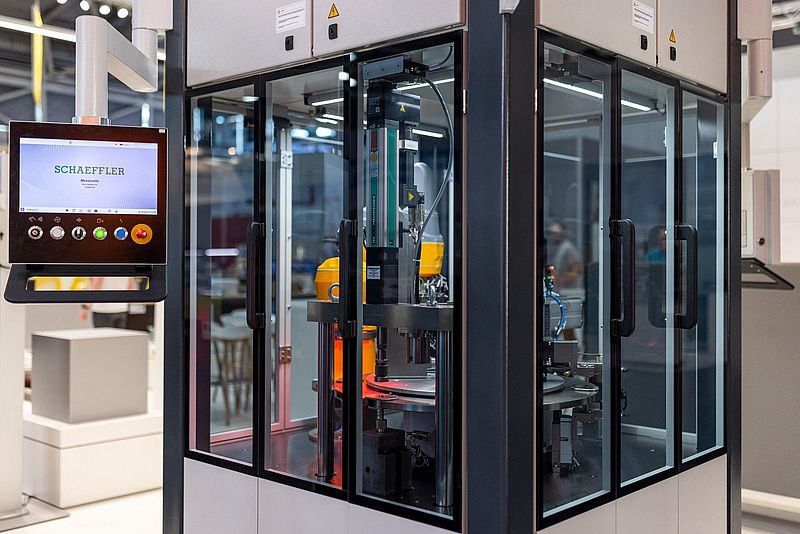
The Schaeffler Group and Siemens have signed a Memorandum of Understanding (MoU) at the Hannover Messe. Both companies will promote the use of artificial intelligence in the industrial sector and thus make a significant joint contribution to shaping the digital production of the future. At the Hanover Fair, Schaeffler and Siemens are once again demonstrated their successful cooperation with the "Siemens Industrial Copilot", an industrial automation solution using AI. It is connected to a production machine from Schaeffler Special Machinery. The AI assistant makes the work of production staff much more efficient. Even complex automation codes for the machine can be generated using natural speech.
“Digitalisation is one of Schaeffler’s key topics,” says Klaus Rosenfeld, CEO of Schaeffler AG. “The use of AI-based solutions is a decisive factor for making production processes more innovative, agile and efficient. With Siemens, Schaeffler has a strong industrial partner at its side to accelerate the development and implementation of generative AI solutions in a targeted manner and to generate added value for its customers.”
“Siemens and Schaeffler are pioneers on the path to highly-automated and digital factories. With the ‘Siemens Industrial Copilot’, we are bringing the capabilities of generative AI to the Schaeffler shop floor,” says Cedrik Neike, Member of the Managing Board of Siemens AG and CEO Digital Industries. “Together, we are showing how artificial intelligence is revolutionising production– from the generation of machine code to AI-based maintenance. And that is just the beginning.“
Industrial Copilot for increased agility and efficiency
Schaeffler is already using a large number of AI solutions in various applications. The “Siemens Industrial Copilot” is operating in pilot mode on a robot cell from Schaeffler Special Machinery, the Schaeffler Group’s special machine construction unit. This project was jointly developed by Schaeffler and Siemens. The AI solution assumes tasks such as creating complex programming codes for manufacturing processes, thus reducing the outlay for machine operators. The “Siemens Industrial Copilot” also has access to relevant documentation, guidelines and manuals to help employees identify potential causes of errors. The AI-based assistant offers further potential with regard to machine correspondence or validations.
Andreas Schick, Chief Operating Officer of Schaeffler AG, says: “We are now at the start of a decade of efficiency at Schaeffler. The ‘Siemens Industrial Copilot’ proves that artificial intelligence can already be used in production today. With the Copilot, we are providing our experts on the shop floor with an innovative digital tool, which simplifies their work and significantly increases their efficiency. We are taking production to a new, digital level in collaboration with Siemens.”
Positive Signals for the Industry from HANNOVER MESSE 2024
More than 130,000 visitors from 150 countries, 4,000 exhibiting companies, 300 startups and over 300 economic and political delegations from all over the world. These are the figures that emphasise the fair's position again after five successful days.
“HANNOVER MESSE 2024 was both an industrial powerhouse and a technology trade fair for the future,” remarked Dr. Jochen Köckler, Chairman of the Managing Board, Deutsche Messe AG, at the closing press conference for HANNOVER MESSE 2024. “It was an industrial powerhouse because visitors found answers to how they can profitably take advantage of automation, artificial intelligence, hydrogen and many other high-tech solutions in their factories, thus making them fit for the future. And it has been a future-oriented technology trade fair, since the innovations that drive industrial competitiveness and sustainability were on display here.”
Highly international visitors
The more than 130,000 visitors from 150 nations traded ideas with some 4,000 exhibiting companies on ways of digitalizing their value chains and making them more resilient. “This means we achieved our ambitious visitor target in a year where HANNOVER MESSE was smaller due to the biennial rotation of several of its component events,” said Köckler. More than 40 percent of visitors came from abroad. Apart from the host nation of Germany, the top visitor nations were China, the Netherlands, South Korea, the United States and Japan.
Dr. Gunther Kegel, President of the ZVEI association and Chairman of the HANNOVER MESSE Exhibitor Advisory Board, stated: “In the current difficult economic environment, this year’s Hannover Messe is a key morale booster. Companies from the electrical and digital industry have impressively demonstrated how innovations, especially the use of artificial intelligence, are opening up new options for more climate protection and greater efficiency in energy consumption and the use of resources. But also for more optimism. We can confidently take on major social challenges such as curbing global warming if we adopt the right measures and consistently pursue the path towards electrification, digitalization and automation. Hannover Messe has once again made the innovative strength of our companies visible and thus made an important contribution to strengthening Germany as an industrial location,” he concluded.
Thilo Brodtmann, Managing Director of the VDMA association, added, “Thinking far beyond day-to-day matters and developing solutions for digital and climate-neutral production – that is the goal of innovative mechanical engineering firms. At this year’s HANNOVER MESSE, they demonstrated how factories can be controlled more intelligently, how climate protection can be achieved more quickly with modern means of production and how autonomous systems can make production safer and more efficient on many levels. In addition, biology and its processes will move into production – the first steps here have already been taken. Hannover Messe remains the best place for all these innovations and for a true spirit of optimism, because manufacturers, customers, political decision-makers and the media come together here in greater numbers than anywhere else.”
From solutions such as the automation of entire production plants, the voice control of machines using AI, the efficient use of hydrogen in industry to the use of software to record and reduce the carbon footprint, HANNOVER MESSE offered a comprehensive picture of the technological opportunities for the industry of today and tomorrow. New fields such as the “biologization” of the economy and carbon management were also brought into focus. And the initiative to create sovereign data spaces for small and medium-sized industrial enterprises under the “Manufacturing X” label is also gaining momentum.
HANNOVER MESSE 2025 runs from 31 March to 4 April. Canada will be featured as the partner country.
Strategic Technology Partnership Formed Between Festo and Phoenix Contact
At Hannover Messe 2024 the two German companies announced their colloboration for development of innovative solutions based on the PLCnext technology.
Festo, manufacturer of pneumatic and electrical automation technology, will use PLCnext Technology, Phoenix Contact’s open ecosystem for modern automation, in future intelligent devices. This will combine the innovative strength of both companies with the aim of taking industrial automation to a new level. The new product generation is expected to be launched by year-end. The integration of PLCnext technology opens up a wide range of opportunities for Festo and its customers:
Openness and flexibility:
PLCnext Technology is based on an open architecture that allows individual solutions to be developed and existing systems to be seamlessly integrated. Festo can therefore offer customized automation solutions for specific customer requirements.
Utilization of synergies:
The combination of know-how from the two companies enables profitable cooperation in order to be able to solve future technological challenges - such as in the area of cybersecurity - in the best possible way.
Innovation and future viability:
The combination of Festo's expertise in automation and PLCnext Technology promises innovative solutions for Industry 4.0. By working together and pooling resources, the challenges of digital transformation can be mastered together.
The common goal of Festo and Phoenix Contact is to meet the requirements resulting from the convergence of IT and OT (Information Technology and Operations Technology) in industry with open automation solutions.
Framework of open platforms
“In a rapidly changing world, it is becoming increasingly important to enter into partnerships and work together within the framework of open technology platforms. A paradigm shift is clearly noticeable. Together with Festo, we will continue to work on generating new solutions for our customers. Because sustainable innovation can only be achieved through close cooperation," emphasizes Frank Stührenberg, CEO of Phoenix Contact.
Festo, a leading company in the industry, has opted for PLCnext Technology. Festo has been looking for a partner with an open system approach for its future direction, who will provide an appropriate operating system, develop it further, and launch it on the market.
"With PLCnext Technology, we are using the technologically leading platform in automation technology. We are convinced that the openness of PLCnext Technology will provide our customers with many advantages," emphasizes Gerhard Borho, Chief Information Technology and Digitalization Officer at Festo. Ulrich Leidecker, COO and President of the Business Area Industry Management and Automation at Phoenix Contact, adds: "The openness of PLCnext Technology opens up the possibility for numerous suppliers to offer flexible, safe and modern automation technology. The technology partnership with Festo represents a milestone for the automation industry. Because the more partners there are in an open automation ecosystem, the more valuable it becomes for each individual participant."
The collaboration between Festo and Phoenix Contact is an important step for the future of the automation industry. New, open thinking and the bringing together of industry expertise sets the course for innovative solutions and drives a sustainable world forward.
About PLCnext Technology
PLCnext Technology is the open ecosystem for industrial automation from Phoenix Contact. With its combination of open control technology, modular engineering software and online community, this solution enables easy adaptation to changing requirements and efficient use of existing and future software services. Together with a digital marketplace for software and systemic cloud integration, PLCnext Technology is up to the challenges of the IoT world.
New Member for the SCHURTER Management Team
SCHURTER is pleased to welcome Steffen Lindner to its leadership team.
Effective 1 April, he will assume the newly created position of General Manager & Vice President EMEA at SCHURTER. In this role, Steffen Lindner will be responsible for all company activities in EMEA, including product management, engineering, sales and production. Appointing Steffen Lindner is an important step for SCHURTER to expand its activities in the key region of Europe as well as Middle East and Africa. With his leadership skills and extensive international experience, Steffen Lindner is ideally suited to lead SCHURTER into the future in the EMEA region and to realise its ambitious goals.
After training as a radio and television technician and completing his studies in electrical engineering / communications engineering, Steffen Lindner began his career in sales at Phoenix Contact. When he took over the Field Device Connector business unit, Steffen Lindner became a member of the Phoenix Contact management team and Managing Director of Phoenix Contact Connector Technology. During his tenure, he was responsible for the successful integration of global product marketing, development and production into the business unit. After two decades at Phoenix Contact, Steffen Lindner joined TE Connectivity Industrial as head of sales for Europe, the Middle East and Africa. He adapted the sales organisation to the changing market conditions and customer needs and introduced a potential-oriented market approach. By strategically focusing on key customers in specific application areas and working in partnership with distributors, Steffen Lindner was able to achieve above average growth with the new organisation. During his nearly seven years at TE Connectivity Industrial, he was involved in several acquisitions and their integration processes.
New Managing Director of TDK-Lambda Germany appointed
Christoper Haase succeeds Gustav Erl, who will retire soon
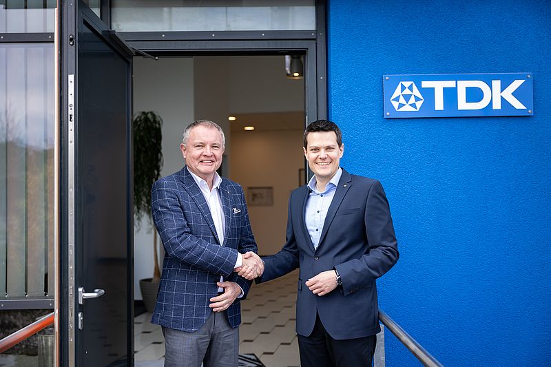
TDK announces the appointment of Christopher Haas as Managing Director of TDK-Lambda Germany, effective 1 April 2024. He has been a member of the Board of Directors since 2012, and in his new role will retain his previous responsibilities as head of the Quality & Compliance organisation in the EMEA region. With over 20 years' experience in the electronics industry, Christopher brings a broad portfolio of technical knowledge as well as entrepreneurial skills, holding an Executive Master in International Business.
“We are delighted to see Christopher assume the role of Managing Director at TDK-Lambda Germany,” says Matt Cotton, Managing Director, TDK-Lambda EMEA. “We are confident that his wealth of experience and expertise will help us to continue to grow and drive towards even greater success within the market.”
Christopher Haase succeeds Gustav Erl, who will retire on 30th June 2024, after 38 years of seniority. On behalf of the entire company, Matt Cotton paid tribute to his 20 years of successful leadership of TDK-Lambda Germany, saying, "Gustav has made a significant contribution to the overall success and development of the company and EMEA organisation during his many years of service. We would like to express our sincere thanks and wish him all the best for the future!"
“I am honoured to step into the role of Managing Director at TDK-Lambda Germany and be entrusted with the opportunity to lead our team of dedicated professionals,” says Christopher Haas. “I am enthusiastic about the progress we are making with our innovative power solutions and look forward to working together with the team on further developments, addressing challenges and driving the continued growth and success of our company.”
Destaco to Become Part of Stabilus Group
American automation specialist complements product portfolio of the motion control specialist
The Stabilus Group, supplier of motion control solutions for a wide range of industries – has completed its acquisition of Destaco, an industrial automation specialist headquartered in Auburn Hills, Michigan, United States. The company was acquired from Dover Corporation, a globally diversified industrial concern that’s also headquartered in the United States.
After an intensive review of strategic fit, both companies signed the purchase agreement on October 11, 2023. Since then, all regulatory approvals have been obtained, and Stabilus SE has acquired 100% of Destaco effective April 2 2024.
Complementary products, integrated solutions
The two partners’ portfolios are complementary. Most importantly, they can be combined to create comprehensive solutions for industrial companies. Whereas products from the Stabilus Group allow for controlled motion sequences and precise vibration isolation, Destaco’s strengths are manual clamps, power clamps and end-of-arm tools for robots, and grippers and indexers for automation. “With our combined solutions, manufacturers can enhance their productivity and build production lines with less integration effort. This is how we tend to capture a larger share of the industrial automation market, which is growing faster than ever before due to the re-shoring of production from emerging markets to the established industrialized nations,” said Dr. Michael Büchsner, CEO of Stabilus SE.
In addition to the good technological fit, there are other synergies between the two partners. Destaco CEO Stefan Eggers affirmed: “The longstanding direct customer relationships and established distribution networks also ideally complement each other. Together, we can scale up our business faster than would have been possible if each were acting alone. In particular, we expect that Destaco will help us boost our European business. Both management and workforce are convinced that this is a win-win situation.”
Strategic building-block for transformation and growth
Destaco generated approximately USD 213 million (approximately EUR 200 million) of revenue in 2022. Founded in 1915, the company develops and manufactures automation, workholding, and remote handling components and solutions in 13 locations across the world.
Smaller Regal Rexnord Induction Motors move to the LEESON® Brand
Regal Rexnord, announces that the LEESON brand of Regal Rexnord will expand significantly as Marathon® NEMA® AC induction motors below 182T frame size are welcomed into the LEESON products family.
Regal Rexnord, announces that the LEESON brand of Regal Rexnord will expand significantly as Marathon® NEMA® AC induction motors below 182T frame size are welcomed into the LEESON products family.
“From the first day of business in 1972, the people behind the LEESON brand have been deeply dedicated to innovating and delivering the highest quality motors to solve our customers’ problems,” said Brooke Lang, Executive Vice President & President of Power Efficiency Solutions at Regal Rexnord. “This integration further deepens the commitment of the LEESON brand to delivering optimized solutions that are engineered to solve our customers’ business challenges through reliability, efficiency and performance.”
No changes of production sites
All Marathon branded motor SKUs below 182T frame size will now be under the LEESON brand name. These include motors used in a wide range of applications. From lifting boats to powering treadmills, pitching machines, running water pumps, HVAC, fans, pumps, conveyors, material handling equipment and food processing equipment. The small motor products will continue to be manufactured in the same plants and the same legacy dedicated LEESON products sales team will be ready and available to serve customers.
From safeguarding warranties to enhancing customer support processes, a dedicated team is carefully managing every aspect of the transition to deliver the benefits of the LEESON brand to current Marathon product users. Known for durable, high-quality motors and solutions, customers can expect LEESON-branded products to meet the highest standards of excellence.
“Customers are at the heart of everything we do,” says Lang. “Our goal is to deliver a better and more consistent experience across our portfolio of market-leading innovative solutions, while making the transition seamless to our valued customers.”
What Is the Right Compute Module for Your Embedded Project
In the realm of embedded computing solutions, Raspberry Pi has emerged as a pioneering force, offering a diverse range of compact modules tailored for industrial and commercial applications. Here we take a look at the differences between the foundation’s Compute Module 4 (CM4) and Compute Module 3+ when it comes to developing embedded projects.
Automation
In the realm of embedded computing solutions, Raspberry Pi has emerged as a pioneering force, offering a diverse range of compact modules tailored for industrial and commercial applications. Here we take a look at the differences between the foundation’s Compute Module 4 (CM4) and Compute Module 3+ when it comes to developing embedded projects.
Raspberry Pi has carved a niche for itself with its versatile array of single-board computers (SBCs), catering to a diverse spectrum of applications ranging from hobbyist projects to industrial-grade solutions. Central to its product lineup are the Compute Modules, compact and modular iterations of the Raspberry Pi boards designed specifically for embedded applications. These modules encapsulate the core processing power, memory, and connectivity features of their larger counterparts, empowering developers to integrate Raspberry Pi functionalities seamlessly into custom hardware designs.
The first version of the Compute Module was released in April 2014, and, up to its third version (CM 3+), it had a 67.6mm × 31.0mm DDR2-SODIMM form factor. In October 2020 - 16 months after the release of the Raspberry Pi 4 Model B SBC - the CM4 was launched too, and, to the surprise of many, it had a new form factor: 55 mm × 40 mm PCB with two 100-pin high-density connectors.
This change opened up for new embedded solutions based on the Raspberry Pi CM but it also made things “interesting” for those who designed products around the old form factor and were accustomed with upgrading to the latest version without any hardware redesign. Luckily, in mid 2022, Raspberry Pi released a Compute Module with the same core of the CM4, but with a SODIMM form factor: the Compute Module 4S (CM4S).
Main Differences
Due to supply chain challenges faced by the industry, the procurement of CM3+ became difficult, and switching to the CM4S was necessary for many industrial adopters.
Here is an overview of the main hardware differences between the CM3+ and the CM4S:
Processing Power and Performance:
At the heart of any computing module lies its processing prowess. The CM3+ is powered by the Broadcom BCM2837B0 processor, sporting four ARM Cortex-A53 cores clocked at 1.2GHz. In contrast, the CM4S boasts a Broadcom BCM2711 processor, featuring quad-core Cortex-A72 cores operating at a blazing 1.5GHz. This boost in processing power translates to enhanced performance and accelerated execution of computational tasks, positioning the CM4S as a powerhouse in the embedded computing landscape.
Memory and Storage Configuration:
Memory and storage play pivotal roles in determining the efficiency and responsiveness of a computing system. While the CM3+ integrates 1GB of LPDDR2 SDRAM, the CM4S offers a superior memory configuration with 1GB LPDDR4-3200 SDRAM, with ECC (Error-Correcting Code) for data reliability. Both the CM3+ and the CM4S provide options for 8GB, 16GB, or 32GB of eMMC flash storage, as well as the "Lite" version for custom external storage.
Form Factor and Connectivity Options
As per above, both the CM3+ and CM4S adhere to the SODIMM form factor, facilitating straightforward integration into custom systems. The interfaces exposed on the connectors are the same, with the notable difference of the HDMI V1.3a of the CM3+ upgraded to HDMI 2.0 in the CM4S.
Power Supply and Voltage Requirements
When it comes to power supply and voltage specifications, the CM4S mandates VBAT (2.5V to 5V) and +3.3V supplies for operation. The +1.8V supply required by older Compute Modules is no longer utilized in the CM4S, although it can be supplied for backward compatibility purposes. This streamlined power architecture ensures efficient operation while accommodating the diverse needs of embedded system designers.
Video and Multimedia Capabilities
The CM4S features an HDMI 2.0 port supporting resolutions of up to 4Kp60. Moreover, it has support for H.265 (HEVC) decoding up to 4Kp60, alongside H.264 decoding up to 1080p60 and encoding up to 1080p30. Coupled with OpenGL ES 3.0 graphics support, the CM4S sets the stage for advanced multimedia applications in embedded environments.
Migrating your application from the Raspberry Pi Compute Module 3+ to the Compute Module 4S involves some considerations.
From a software perspective the move from 3+ to 4S is relatively painless, as Raspberry Pi OS images should work on all platforms. Of course it needs to be updated to a version supporting the 4S. Specifically a Linux kernel version 5.10 or above is required. Keeping your OS up-to-date is anyway good practice even if sticking to the same core.
On early releases of the OS supporting the 4S version, the USB 2.0 interface used by the I/O board (and other products embedding the CM) was not enabled by default. As a result devices would not show up on the network when booting as the Ethernet controller is connected to the USB bus, and those who attempted a boot from USB did not succeed.
The issue could be easily solved by adding the following line to /boot/config.txt: dtoverlay=dwc2,dr_mode=host
Speaking of USB boot, an interesting difference on the CM4S is that USB and network boot are enabled by default. For device provisioning (especially when done in high volumes) this is a very handy addition as booting and/or flashing a unit no longer requires the use of rpiboot and an I/O board with a USB slave interface, which are instead required for the CM3+.
So, for instance, a plain vanilla Strato Pi CM by Sfera Labs with no OS installed, can now be flashed with a custom image by simply plugging a bootable USB stick in one of its ports (no need to open the case), power it up, access the unit via SSH, and write to the internal eMMC.
Finally, on the CM4S, enabling boot options and modifying priority sequences can be conveniently done by editing the bootloader configuration, which is written in the module's EEPROM (check the rpi-eeprom-config command). On the CM3+ this requires writing to the OTP (One Time Programmable) memory, which cannot be undone, and possibly toggling some GPIOs using external hardware.
Long-term availability for industrial applications
The introduction of the Raspberry Pi Compute Module 4S has addressed the need for a migration path for industrial adopters facing supply chain challenges with the CM3+. With its enhanced processing power, memory configuration, and advanced multimedia capabilities, the CM4S offers a significant upgrade for embedded computing applications. While transitioning from the CM3+ to the CM4S may require some work, the benefits of improved performance and expanded features make it a worthwhile investment for developers and designers alike.
Sfera Labs was the first industrial manufacturer to introduce support for CM4S in August 2022, only a few months after its launch by Raspberry Pi. Sfera Labs launched its first server based on the Compute Module, the Strato Pi CM, in 2018. Strato Pi CM is a compact industrial server CE/FCC/IC compliant, with a wide-range power supply, eMMC Flash, RTC, RS-485, watchdog, and secure element. In 2019, the Strato Pi CM Duo followed, the first Raspberry Pi-based server offering a dual SD card slot. This feature is critical for high-reliability systems, which must guarantee a functional life cycle of many years. In addition to ensuring data integrity and redundancy, Strato Pi CM Duo can perform a remote full-system upgrade.
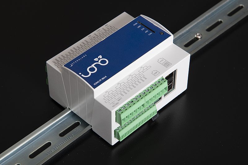
Furthermore, in 2020, Sfera Labs launched Iono Pi Max, an all-in-one solution for industrial control with a Raspberry Pi core. Iono Pi Max features an incredibly wide range of analog and digital interfaces: four 4 mA to 20 mA and four 0 V to 10 V, galvanically isolated, highly accurate inputs to connect standard industrial probes, as well as two additional inputs specific for Pt100 and Pt1000 temperature sensors. Six digital inputs, accepting up to 30 V signals, let users integrate digital counters and general status signals.
The Strato Pi CM, Strato Pi CM Duo, and Iono Pi Max support all the Raspberry Pi Compute Module versions: 3, 3+, 4S, opening the door for new, advanced applications while safeguarding existing developments.
Sfera Labs’ Exo Sense Pi is based on CM4. The Exo Sense Pi is a multi-sensor module with an extensive range of connectivity options. These options are ready for residential and commercial applications, such as environmental monitoring and data gathering, BLE positioning, indoor people and assets tracking, room management and access control, voice control, and much more.
Author: Giampiero Baggiani, Co-Founder and Head of Software Development at Sfera Labs
Cloud Platform for Remote Management of Edge Devices
Private cloud architecture for secure industrial deployment
Automation, Industry 4.0
Aetina announced the launch of the EdgeEye cloud-based management platform. The platform aims to simplify edge computing device management, helping enterprises improve operational efficiency, resilience, and cost-effectiveness. Edge devices often face challenges such as system instability and crashes, especially when operating in harsh outdoor environments such as earthquakes or extreme temperatures. Therefore, real-time system monitoring and prompt effective troubleshooting are crucial.
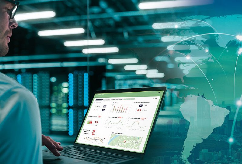
EdgeEye adopts a browser-based platform, providing an intuitive and user-friendly management dashboard accessible via smartphones, tablets, or laptops. The platform supports out-of-band (OOB) management, allowing management even in offline situations, while continuously monitoring device operation status through in-band management technology. With both in-band and out-of-band management, EdgeEye enables remote data collection, system monitoring, remote troubleshooting, and power cycling, thus avoiding the risk of prolonged device downtime.
Private Cloud Architecture
Moreover, as awareness of cybersecurity and protection of business confidentiality increases, many enterprises are turning to private cloud architectures to prevent data leaks. Built on a private cloud architecture, EdgeEye allows enterprises to deploy EdgeEye servers within their own domains to ensure data security and privacy.
In smart city scenarios, such as traffic surveillance devices spread across the city or the rapid rise in recent years of large-scale green energy devices like solar and battery equipment, troubleshooting and system rebooting by technicians incur not only manpower costs but also difficulties in responding to device downtime in real-time. EdgeEye can simultaneously monitor multiple devices. Once system abnormalities are detected, EdgeEye will proactively send warning notifications, enabling real-time remote rebooting and troubleshooting. This reduces manpower and maintenance costs, thereby enhancing the efficiency of device management in the AI era.
With its comprehensive portfolio of edge AI products, Aetina integrates years of AI application experience to create the most suitable solution for customers, making remote device management easy and effortless.
Collaborative Robot Series With up to 30 kg Payload
Precise and fast movements for a versatile range of applications
Automation
Delta Electronics announced a significant milestone in its development of smart manufacturing solutions with the launch of six highly versatile models in the D-Bot series of collaborative industrial robots (Cobots). The portfolio features Cobots with payload capacities up to 30 kg, reach spans up to 1800 mm, compatibility with EtherCAT, Modbus and CODESYS, as well as the integration of 24-bit encoders to ensure optimal levels of precision, especially in pick & place, welding and palletizing applications.
Speed, Precision, Easy Integration, and Safety Combined
The D-Bot series includes six versatile models: D-Bot 6, D-Bot 8, D-Bot 10, D-Bot 16, D-Bot 20, and D-Bot 30, with payload capacities ranging from 6 to 30 kg. Featuring six axes for unmatched flexibility and precision, these models offer speeds up to 200 degrees per second and accuracy within ±0.02mm. The integration of 24-bit encoders enhances precision, ensuring consistent performance.
The series is designed with IP66 protection and advanced safety protocols. Supporting interfaces like EtherCAT, Modbus and CODESYS, these cobots are perfect for a range of tasks, from palletizing, pick & place, welding and more. With "Plug & Play" setup and intuitive programming via a user-friendly interface, the D-Bot series are accessible to operators of all skill levels, promoting human-robot collaboration in sectors such as automotive, logistics and electronics.
Rapid Deployment and Easy Operation
Delta's D-Bot series are designed for rapid deployment, requiring no special programming skills, making them operational in no time. Setting up movements and command executions is effortlessly achieved. Furthermore, the system facilitates teaching through drag & drop, Python, ROS 1, or C++, ensuring a simple and flexible operation. The modern graphical user interface (GUI), featuring immersive 3D visualization, allows users of all levels to quickly program. The inclusion of an HMI panel in the package eliminates the need for additional devices or tools for control, streamlining the operation process even further.
How Small Manufacturers are Building a Business Case for Robotics
Smaller manufacturers are the fastest-growing area of industrial robotics today, driven by the need for new collaborative robotics systems.
Automation
Small manufacturers are gaining the scale, speed, and quality advantages they need to compete and win against larger competitors through automation and robotics. They’re gaining that competitive advantage by using robotics to automate time-consuming tasks across shop floors. This frees manufacturing teams to spend time on work that delights customers and delivers higher margins. The bottom line is that automation and robotics allow small manufacturers to compete, win more deals, and solidify customer relationships as effectively as their larger competitors.
Industrial robots used by small manufacturers
Seeing an opportunity to expand their systems and solutions markets, robotics providers are fast-tracking intro-level robotics machinery, programming, and robotics-as-a-service offerings. The average price of an industrial robot has halved over the past decade. It was around $23,000 in 2022 from $47,000 in 2011, according to ARK Invest. They predict that costs will fall a further 50% to 60% by 2025.
Why small manufacturers are turning to robotics now
Smaller manufacturers are the fastest-growing area of industrial robotics today, driven by the need for new collaborative robotics systems. The global market for industrial robots is expected to grow at a compound annual growth rate (CAGR) of 9.39%. It is estimated to reach a total market value of $30.5 billion by 2030. The collaborative robot segment, core to small manufacturers due to flexibility and adaptability, is growing with a CAGR of 14.7%. In 2022, this segment generated $ 715 million in revenue, projected to surpass $2.1 billion by 2030.
A plan to address challenges and improve optimization
To address challenges and improve optimization in robotics, a small manufacturing company can consider the following reasons on why turning to robotics is beneficial:
Labor shortages, fluctuating material availability and costs, and progressively tighter customer quality standards drive small manufacturers to automate more of their shop floor operations.
Labor shortages in remote regions of North America where production workers are scarce are where robotics is flourishing in small manufacturing companies. The Harvard Business Review’s recent article A New Generation of Robots Can Help Small Manufacturers observes that “manufacturing especially is having huge problems recruiting and retaining employees. More than 2 million manufacturing jobs will sit unfilled across the United States by the end of this decade, and three-quarters of European companies already have difficulty recruiting suitable workers. Workplaces are crying out for talent and face decreased productivity and unsustainable staff turnover.”
A plastics manufacturer located in a remote region of the Pacific Northwest couldn’t recruit enough production workers to handle the orders they’d received from their best customers, so they decided to start piloting robotics.
The manufacturer invested in two robotics stackers, sorters, and end-of-arm extensions on their robots to fulfil diabetic test kit orders for a leading European biomedical manufacturer. Running three shifts a week with the stackers and end-of-arm extensions, they delivered their largest order of 150,000 kits a week.
Robotics in small manufacturers are delivering measurable results at scale. Building a business case for robotics factors in all associated costs and benefits. The following are a few of the many measurable benefits that robotics is delivering for small manufacturers today. Reducing maintenance costs by 10-40%, increasing productivity by 3 to 5%, and reducing time-to-market for new products by 20 to 50% are a few of the measurable results robotics is delivering. The cost savings extend to quality control and inventory holding, with reductions of 10-20% and 20-50%, respectively. Furthermore, the automation of knowledge work can lead to a productivity increase of 45% to 55% for technical professionals.
Building a business case for robotics
Automating the most time-consuming areas of production to reduce costs and improve quality is the goal many companies initially pursue when they adopt robotics. Start small with those areas draining cash and time from operations – they will show the greatest gains from automating them with robotics.
Define a strategy for implementing robotics across the shop floor that will deliver measurable results at scale. Knowing that the investment in a robotics system is paying off and tracking how much helps strengthen and defend the business case for future automation projects.
Here are the steps small manufacturers take in building a business case for robotics:
Identify Pain Points. The first step is to identify the most time-consuming and labor-intensive tasks in the manufacturing process. These are the areas where automation can provide the most significant benefits. For example, pain points could include supply chain disruptions, labor shortages, regulatory compliance, inefficient processes, or productivity issues.
Evaluate Potential Solutions. Once the pain points are identified, evaluate the different robotic solutions available. Manufacturers often create comparison tables in Google Sheets or Excel to compare cost, ease of implementation, and potential return on investment.
Calculate ROI. Calculate the Return on Investment (ROI) for the proposed robotic solution. This involves determining the initial cost of the robot, ongoing costs, labor cost savings, increased productivity, and potential tax incentives. The ROI is typically calculated over a horizon of 5 to 10 years, considering an industrial robot can work for an average of 15 years.
Complete initial pilot testing. Implement a small-scale pilot project to test the effectiveness of the chosen robotic solution. This allows manufacturers to assess the real-world benefits and challenges of automation.
Measure and share results with production teams. Track the performance of the pilot project, focusing on key metrics such as productivity, quality, and cost savings. This data will be crucial in building a compelling business case.
Scale up across the shop floor. If the pilot project is successful, plan for a larger-scale implementation. Consider the necessary resources, timeline, and potential impact on the overall operations.
Review and adjust. Continually review the performance of the robotic systems and make necessary adjustments. This ensures that the automation strategy remains effective and continues to deliver value.
Author: Louis Columbus, Senior Industry Marketing Manager at DELMIA
Compressed Air with Energy Efficiency at the Core
It is not a revelation to anyone in the industry that energy is the largest operating expense, accounting for the majority of utility costs. In manufacturing processes using compressed air, air compressors consume approximately 12% of the total electrical energy, and over the lifespan of an air compressor, 80% of the cost is energy use, and 20% is the cost of the unit including maintenance. Energy...
Energy Efficiency
It is not a revelation to anyone in the industry that energy is the largest operating expense, accounting for the majority of utility costs. In manufacturing processes using compressed air, air compressors consume approximately 12% of the total electrical energy, and over the lifespan of an air compressor, 80% of the cost is energy use, and 20% is the cost of the unit including maintenance.
Energy consumption reduction targets across the European to be achieved by 2030. The revised EU Energy Efficiency Directive (EU) 2023/1791, published in September 2023, will accelerate energy efficiency across the European Union, requiring EU countries to collectively reduce their energy consumption by 11.7% by 2030, relative to the 2020 reference scenario. Additionally, EU countries will have to achieve new annual savings of on average 1.49% of total energy consumption from 2024 to 2030 (https://energy.ec.europa.eu/news/new-energy-efficiency-directive-published-2023-09-20_en).
Embracing energy efficiency practices is much more than compliance. It is also the right thing to do. Decarbonisation of heavy industrial processes is central to reaching targets combatting climate change. With industry being the third-largest carbon contributor after energy production and transport, energy efficiency measures in industrial processes have enormous decarbonisation potential.
This article examines ways to consume less energy, produce more, and bring lasting benefits in terms of sustainability, profitability, and effectiveness to your compressed air applications.
An informed, holistic view – Air Audit
Whether you’re considering a new air compressor or planning to upgrade the existing system, working closely with a subject matter expert capable to design or redesign your compressed air systems, one that could then remain as your service provider, is critical. This will ensure you get the true picture of all areas that need to be addressed when aiming at improving the energy efficiency of your operations.
Your expert partner would conduct a compressed air system energy audit, or Air Audit to identify areas of loss or inefficiencies within a compressed air system. Moreover, skilled energy audit engineers can then identify and modify faults and disorders.
A complete analysis looks at everything from the compressor to the environment in which it operates, as well as operational demands such as peaks and troughs in air demand and operational expansion planning. A finite analysis of the bigger picture - understanding how even the most minor system elements impact the energy consumption associated with the compressor.
The aim is to strike the right balance in technical and economic choices - in compressor units, capacities, operational parameters, energy efficiency, planning for future air demand changes, and considering all energy costs.
A proper Audit Report details recommendations on short-, medium-, and long-term measures for energy conservation, along with financial estimates and analysis for their implementation. These recommendations come with databases and fact sheets generated by measurements and tests conducted in your plant and the field. After this study, manufacturers can propose making educated decisions about their assets, upgrade investments, and ultimately achieve a reduced compressed air energy consumption.
Sizing the air compressor and selecting the right technology
With so many air compressor technologies in the market today, the right selection for your production can be overwhelming. When choosing an air compressor, assessing the load type is critical. For example, a screw air compressor doesn't shut down immediately and goes into unload state to limit too many motor starts and stops. This unloading process consumes up to 30% of energy, increasing the company's operating costs. When selecting the unit for your facility, duty cycle, operating pressure, and airflow demand should be some of the key considerations.
Different industries like pharmaceuticals, automotive, food and beverage, etc. are powered by various pneumatic applications that demand a specific airflow (m³/min). Selecting a suitable compressed air system is crucial to ensure that the air compressor meets the airflow and pressure demands of the pneumatic applications while ensuring optimal performance and energy consumption.
The duty cycle, referring to the operation cycle or the time the compressor runs to provide compressed air at a consistent pressure and specific flow rate, is one of the critical parameters that help decide if a fixed speed drive or a variable frequency drive (VFD) is required. Manufacturers can choose from a wide range of air compressors equipped with or without a VFD based on the variation in airflow demand.
In the case of a fixed-speed air compressor, the compressor runs at the same rate, consuming the fixed power for the air demand. The electrical motor runs at the maximum constant speed irrespective of the compressed air requirement. On the other hand, the air compressor with variable frequency drive can automatically adjust the speed between its minimum and maximum range, ensuring that the compressed air generation matches the compressed air demand and subsequently consumes significantly less energy at low demand. The VFD air compressor greatly benefits industries and applications with largely varying airflow demands. However, it’s not a given that a VFD compressor is the better technology in all cases. It’s important to look at the size of the air receiver that provides a certain buffer capacity. This air receiver will ultimately handle smaller flow fluctuations and therefore will be very beneficial to avoid too frequent starts of the compressors, and even help VFD compressors as too fast of air demands will lead to quick pressure drops which the VFD cannot cope with. Therefore, there is a good consideration to be done when auditing and changing eventually the system after an audit.
When pressure drops
Selection of the right compressor can be a daunting challenge with several technologies and options available in the market. Looking at the quality of air requirements, the capacity of the compressor, duty cycle, and utilisation together with your compressed air partner will help you choose the right solution. Whether it’s reciprocating and screw compressors, VFD, or Fixed Speed technology, one of the other factors to look at is the overall design of the system and reduction of pressure drops – the reduction in air pressure from the compressor discharge point to the application point of usage.
High-pressure drop in the distribution system and the hoses, pipes, and joints results in lower operating pressure to the user and thus results in additional pressure generation and a significant increase in energy consumption.
The most typical areas where “Pressure drop” occurs include the pressure vessel, aftercooler, air treatment equipment like dryers, filters, check valves, and the piping system itself. For every additional 1 bar increase in discharge pressure, there will be an additional energy consumption of approximately 7 percent of the full load power. Additional generation of pressure will also lead to additional storage capacity and increase the cost of equipment.
Pressure drop upstream of the compressors created by the inlet air filter system results in higher power consumption. A pressure drop downstream will induce the need to select a compressor system that generates a higher pressure. Air pressure optimisation, and minimising differentials in all parts of the system are important criteria for efficient operation and saving energy.
If a certain side application requires a much higher or lower pressure, it is advisable to use a separate compressed air system for that pressure rather than expanding or boosting the compressed air from the central system in a factory. The ROI of a separate system will be economical compared to the overall energy savings that the plant would generate by optimising pressure requirements.
Choosing the right components in a compressed air system
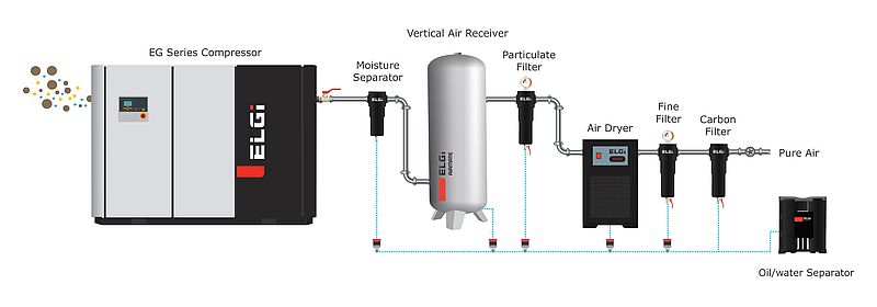
Compressed air contains inherent impurities that are detrimental to the end application. Some common contaminants of compressed air are water, dirt, small wear particles, bacteria, and sometimes even degraded lubricating oil. For increased reliability and energy savings, compressed air must be clean and dry. Choosing the right product from a wide range of pneumatic downstream and upstream accessories can make the air friendly to the environment, end-use, and your pocket:
- Moisture and water vapour precipitate as condensate when compressed air cools down following a compression process. Dryers eliminate and remove this condensate from the compressed air system to prevent damage to downstream equipment.
- In the case of oil-lubricated screw compressors, the process of compressing air results in the formation of condensate, a mix of water, oil, and dust particles. To avoid polluting the groundwater, it is necessary to treat the condensate before disposal into the wastewater system. An Oil Water Separator can be easily integrated into any installation and removes oil in the condensate through a multi-level separation process with both efficient, absorbent fibre and activated carbon, only using gravitational energy.
- Atmospheric air contains moisture, particle contaminants, microorganisms, and gases. When it is compressed, the concentration of these elements increases by 6 to 10 times. When it is compressed by an air compressor, oil, and metal traces get added during the compression process. Reliable filtration solutions remove contaminants from the compressed air providing assurance of purity before it is used for any application. The filter element enables high contaminant removal with low-pressure drop, also resulting in energy savings.
- Heat Recovery Systems (HRS) enable to recover up to 78% of the heat generated during the process of an oil-injected air compression and are available for operations of all sizes. This heat can be used to heat water, which can be useful in the production process, boiler feed, or for domestic water usage. A high return on investment brings immediate cost savings and more importantly, saved energy contributes to carbon emission reductions and helps you in lowering the company’s net carbon footprint.
- Zero loss drain valves remove the condensate formed in the production of compressed air, which gets collected in dryers, after-coolers, and air receivers and may cause rust or damage in the system. Automatic Drain Valves are designed to fit directly on the equipment and sense the level of condensate to prevent compressed air losses in the system.
There is a plethora of elements, products, and solutions to consider when looking at improving the energy efficiency of your systems. Partnering with the experts in compressed air for a detailed examination of your system and finding the right balance in technical and economic choices to protect yourself against rising energy costs and more stringent energy efficiency regulations will pay off in an increasingly shorter timeframe these days.
Author: Niccolò Casini, product manager ELGi Compressors Europe
Modular Synchronous Generator in the 20 MW Class
For flexible backups in the energy transition
Energy Efficiency
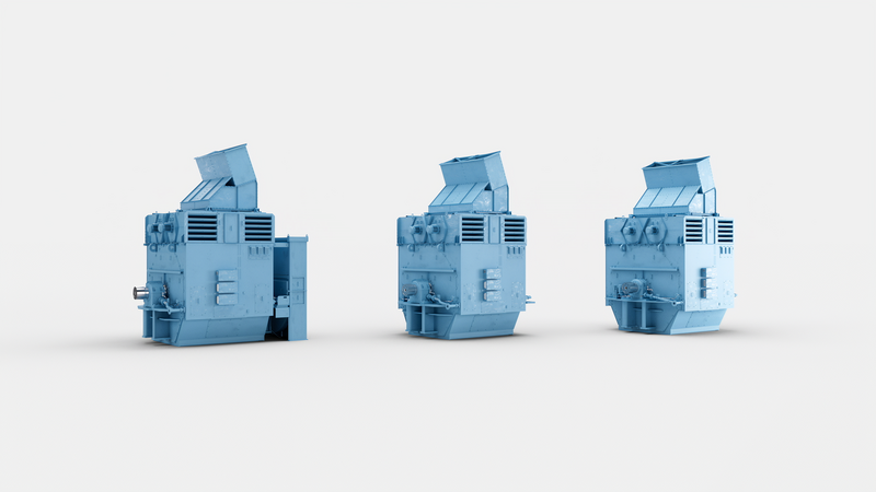
ABB has developed the new Modular 20-megawatt (MW) class synchronous generator as a flexible, scalable approach to balance power grids as they transfer an ever-increasing amount of renewable energy. In contrast with previous designs intended for continuous output only, the modular platform can be configured for various operational profiles. These range from short-term, peak shaving, through intermediate operation to traditional, continuous baseload generation. The new synchronous generator also offers the capability to increase the inertia available by incorporating flywheels.
“Growing levels of intermittent and variable renewable energy resources (RES), such as wind and solar are creating increasingly challenging conditions for power grids. Hence the growing need for reliable generators designed to maintain the balance essential for resilience and security of supply,” says Markku Väinämö, ABB Global Product Manager, Generators. “That is why we have worked with some of the global leaders in engine power plants to develop this innovative platform. It offers the adaptability essential to support a new generation of operational profiles and applications.”
In addition, generating sets often need to meet country-specific grid code requirements before they should be connected to electricity networks and the Modular synchronous generator is fully grid-code compliant. Another demanding requirement is to stay connected during a low voltage or short-circuit event in some part of the grid. This calls for high inertia to ensure that the plant stays synchronized with the grid when the fault is cleared, and voltage returns to nominal. To support this requirement, the Modular synchronous generator has an option to add inertia by incorporating additional flywheels.
Modular construction, together with ABB’s extensive global supply chain footprint enables the new generator to be delivered within shortened timescales. It is also designed to support easy transportation and installation.
Using the Modular synchronous generator in peak-shaving or intermittent operational profiles typically means that the running hours are shorter compared to traditional continuous operation. This reduces the demand for cooling. Therefore, the new design also features an upgraded cooling unit which can be operated only as needed.
Universal Regenerative Unit
Intelligent energy recovery for maximum efficiency
Electronics & Electricity, Energy Efficiency
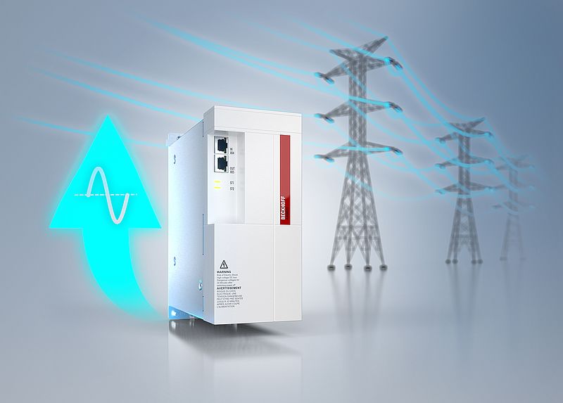
The AX8820 universal regenerative unit from Beckhoff is used to feed regenerative energy back into the grid. It is suitable for use with the AX8000 multi-axis servo system, AX5000 digital compact servo drives, and third-party devices. The energy is regenerated sinusoidally, preventing the grid distortions that are common with block-shaped regeneration. The AX8820 is designed for a nominal supply voltage of 400 to 480 V AC, nominal output of 7 kW, and a maximum DC link voltage of 848 V DC. For effective energy management, the regenerative energy is initially stored in the DC link. The AX8820 only starts feeding power back into the grid just before the overvoltage threshold of the connected devices is reached. Several AX8820 regenerative units can be operated in parallel to optimally adapt the regenerative power to the needs of the machine.
Diagnostic data use for optimized results
No communication via EtherCAT is required to carry out energy recovery. However, extended parameterization – to adapt the voltage levels to the connected devices, for example – is possible via EtherCAT. With the help of the extended diagnostics via EtherCAT, the current regenerative energy can also be analyzed. The online data can be used to record the timing of the machine processes. This means that an investigation to see whether the efficiency of the machine can be increased by staggering the machine processes can be performed.
Power Supply with Integrated Electronic Circuit Breaker
Three-phase version with up to 40A output current
Electronics & Electricity
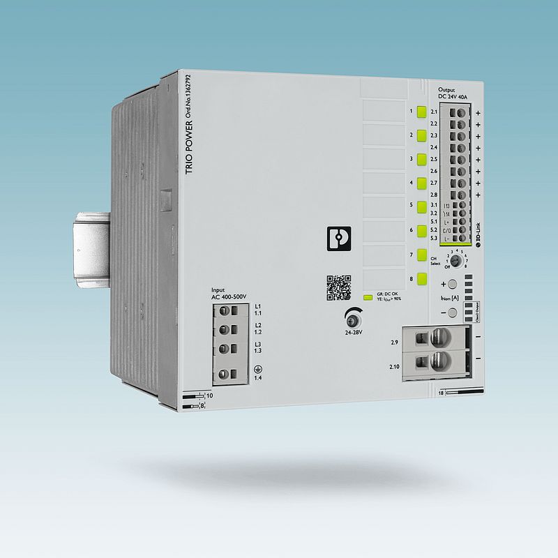
The third generation of Phoenix Contact's Trio Power power supplies is available for machine builders. The power supplies are compact, robust, reliable, and impress with easy handling. The new three-phase power supplies with integrated multi-channel device protection feature a space-saving design and are now also available up to a 40 A nominal output current. The units also feature particularly easy handling with push-in connection technology for quick and tool-free installation. Integrated marking fields can be used for easy EID and circuit marking. Due to an intuitive commissioning concept, the devices are quickly ready for use. The mechanical lock of the potentiometers ensures that the devices are also tamper-proof.
Easy diagnostics
Furthermore, the power supplies feature smart diagnostic options: multicolor LEDs and a collective relay contact signal all relevant states. The remote reset function enables the output channels to be reset via the digital input. IO-Link communication facilitates detailed diagnostics and parameterization. The dynamic boost (150%/5 s) also enables difficult loads to be started. Intelligent self-monitoring and integrated load management ensure high system availability.
Programmable DC-Power Supply Series
One-, two-, and three-channel models supplying up to 32 V, 10 A and 100 W DC power
Electronics & Electricity
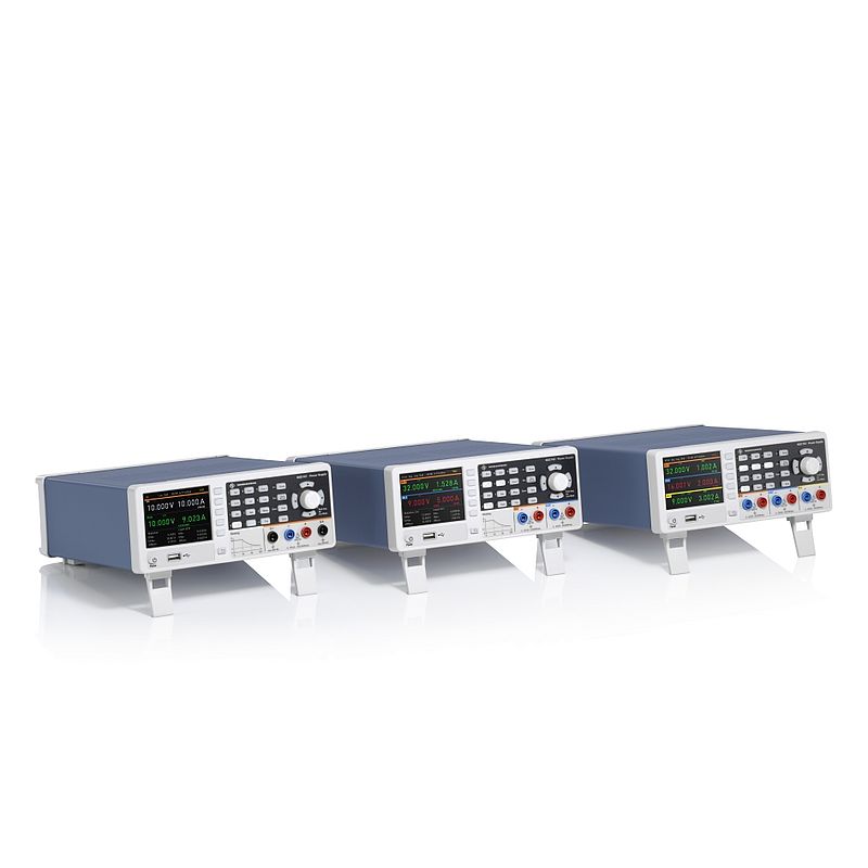
DC power supplies are essential throughout the electronics industry to provide the basic requirement of accurate and stable DC power from an AC source that may be subject to fluctuations and surges. The new Rohde & Schwarz NGC100 power supply series not only meets this fundamental requirement, but also includes features, functions, and remote-control capabilities to support applications far more complex than steady output power. The series includes one, two, and three-channel models supplying 0-32 V per channel at up to 10 A and 100 W power output. The single-channel R&S NGC101 delivers up to 10 A, the two-channel R&S NGC102 up to 5 A per channel, and the three-channel R&S NGC103 up to 3 A per channel. Small and light, two R&S NGC100 can be mounted next to each other in a 19” rack to optimize test setup footprints.
Each channel in the two and three channel models is fully isolated for maximum flexibility. Users can use the channels independently as fully independent, extremely compact power supplies. Or they can combine the channels in series to increase the maximum potential difference to 96 V, or in parallel for currents up to 10 A. Full galvanic isolation means that channels can be connected to supply balanced circuits without worrying about grounding complications.
Programmable changes
The basic performance of the R&S NGC100 as a power supply is excellent, both in terms of output range and output quality regarding low ripple and noise. The application support and additional features exceed expectations for this class of instrument. The remote sensing function ensures accuracy as users measure the voltage at the input of the circuit being powered, not at the output of the power supply. Users can also program voltage or current changes for a test sequence or avoid steep ramp-ups to protect the device being powered, or simulate operating conditions.
The R&S NGC100 puts safety first by providing a full range of protective functions for electrical and thermal properties. Users can set the time and define sequences for switching on channels. Voltage and current values for the circuit to be powered can be logged. All models of the R&S NGC100 have a standard dual interface with USB and LAN ports, and an optional GPIB interface is available for remote control. For external control, a digital trigger supports input in Transistor-Transistor-Logic format to trigger functions such as logging. It is also possible to input sequences of voltage or current changes from an external program. An analog interface with a maximum input of 10V and 20 mA controls near-immediate changes in output voltage or current across the full range.
Solutions for Low Flow Liquid Measurement
The measurement of low flow is becoming widely used in many industries. However, the smaller the flow, the trickier it is to control and measure, and finding a suitable flow measuring technology at reasonable cost can prove challenging for both users and flow sensor manufacturers.
Sensor Technology
The measurement of low flow is becoming widely used in many industries. However, the smaller the flow, the trickier it is to control and measure, and finding a suitable flow measuring technology at reasonable cost can prove challenging for both users and flow sensor manufacturers.
There is no set definition for ‘low flow’ in terms of measurement limits for fluidics handling. However, low-flow applications encounter amplified flow stability and performance issues not seen in larger flows. The minimal liquid volume being measured in low flows renders them highly sensitive, such that even the slightest disruptions in process or ambient conditions can exert a substantial impact on flow stability. Within the markets Titan Enterprises operates in, we consider low flow rates as those below 50 ml/min, with many customers seeking flow rates of between 2 and 20 ml/min.
Transport of concentrated liquids boosts increased need for measurement solutions
Neil Hannay, Titan’s Senior R&D Engineer observes: “We are certainly seeing an increase in demand for low flow measurement technologies driven by various industries moving towards transporting heavily concentrated liquids, which are then diluted at the point of use. This translates into huge savings on transport and storage costs and also has a positive environmental impact.”
Whether cleaning fluid additives, syrups and flavourings for beer or soda, chemical additives for oil and fuel, paint pigments or administering drugs, low flow flowmeters are required to dose these concentrated fluids at the end process, dispensing the precise amount of liquid to the correct dilution.
As mentioned, measuring low flow is a challenging application to satisfy. The amount of energy available in low liquid flow is unlikely to be sufficient to drive most mechanical flowmeters to give linear results. By comparison, electronic flow meters can be limited by sensitivity, zero drift and slow response times. Here we analyse 5 types of flow meter - Ultrasonic, Turbine, Oval Gear, Thermal and Coriolis - and their suitability for low flow measurement:
Ultrasonic
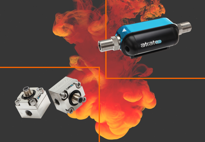
Ultrasonic flowmeters measure the velocity of flow. Titan's in-line Atrato© models, using patented time of flight technology, are capable of measuring flows down to 2ml/min. Lower flow rates equate to smaller signals to determine flow rate and as such, this lower signal strength can affect the flowmeter’s capability to produce repeatable measurement results.
Design challenge: Straight-forward engineering vs complex electronics.
Advantages: High accuracy; not fluid specific; high signal to noise ratio; no pressure drop requirements; suitable for both turbulent and laminar liquid flow.
Disadvantages: Susceptible to process vibrations/pulsations/noise; sensitive to gas.
Turbine
The energy required to spin the rotor of a turbine flowmeter becomes swamped by the drag from the system at low flow rates. As flow rate reduces and transitions from turbulent to laminar flow, the linearity changes and the measurements become less accurate. Pelton wheel turbines that use low friction, precision bearings can mitigate this effect to some degree and with careful design, are capable of flows down to 1-2ml/min. They are capable of fast response times and operate across wide flow and operating temperature ranges.
Design challenge: Straight-forward electronics vs complex precision engineering.
Advantages: Low cost; can be calibrated in-situ; good accuracy and repeatability with rapid response times.
Disadvantages: Susceptible to changes in fluid properties; requires sufficient pressure to move liquid through the pipeline at a rate that causes the turbine blades to spin.
Oval Gear
Positive displacement flow meters, such as oval gear meters, are particularly effective for measuring low flow viscous fluids, although the resolution can be quite low. To obtain good resolution, the oval gear meters need to be small in low flow applications. Installing an oval gear meter in a horizontal position will reduce rotational friction and improve low-flow measurements. The lower the flow, the smaller the gear size, which are manufactured to tight tolerances with small internal clearances to minimise any fluid leakage around the gears.
Design challenge: Straight-forward electronics vs complex precision engineering.
Advantages: Ideal for viscous liquids, precision chemical dosing; good reliability.
Disadvantages: Not suitable for low flow aqueous solutions as the slippage past the moving element is greater than the volume being measured. Trapped air can prevent small gears from rotating – ensure all gas is purged on initial startup. Low resolution.
Thermal
Thermal flow sensors, primarily used for monitoring gas flow, operate on the principle of monitoring thermal transfer using a reference temperature, a heat injection and a detector. The basic approach is that heat is added to the flowing stream and a temperature imbalance being used to obtain a flow rate. They are fluid-specific as the technology relies on the liquid’s thermal properties and are generally calibrated for the specific fluid properties.
Design challenge: Relatively simple engineering vs complex electronics.
Advantages: Highly sensitive and able to measure flow rates down to nanolitres per minute; suitable for low pressure drop applications; not so reliant on the dynamics of the fluid to make a measurement.
Disadvantages: Fluid-specific. Thermal low-flow liquid flowmeters are non-linear over their temperature range and so require some correction during the process. Not suitable for low boiling point liquids or liquid mixtures with changing composition.
Coriolis
The Coriolis is a mass flowmeter, i.e. measures mass flow directly and independently of the liquid’s properties. The Coriolis provides mass flow and density measurements that are both repeatable and highly accurate, even when the composition of the liquid is unknown or changing. Using the principle of accelerating a moving fluid and detecting the reaction on the vibrating tube with sensors, Coriolis meters are very sensitive and flows lower than 0.2 ml/min are possible.
Design challenge: Complex electronics and engineering.
Advantages: Extensive material compatibility; can be used for either liquid or gas flow measurement; independent of liquid or process variables.
Disadvantages: The primary limitation is the flow must be single-phase and of low viscosity. They are also expensive devices so would not be suitable for low-cost low flow applications.
As flowmeters can be the most limiting component of a low flow fluidic system, it is essential to choose the most suitable high-precision flow sensor for an application.
Digital Transmitter for Weighing Applications
High Speed and Accuracy with options for system redundancy
Automation, Sensor Technology
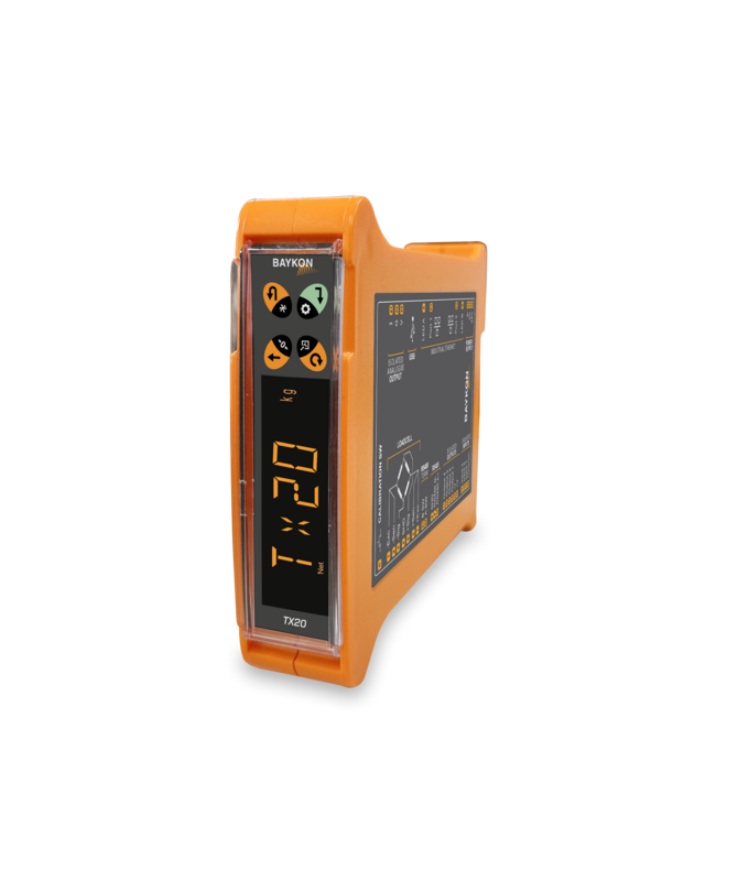
Baykon TX20 series digital transmitters are designed for force, moment, and pressure measurement processes in addition to static and dynamic weighing. They transfer precise measurement information acquired at a high conversion rate to your PLC/SCADA/PC system in the most accurate and fastest way with industrial communication protocols. All products with Ethernet output are dual-ported to provide Ethernet daisy chain connection. TX20 can also be connected to Profinet Redundant S2 systems directly. 3 digital inputs, 4 digital outputs, and analog outputs are available as additional connection options.
Baykon TX20 transmitters are manufactured identically to each other and individually calibrated. Thanks to this feature, they can be replaced directly without needing any adjustment in the counting mode, and in the weight mode error on the electronic calibration because of replacement is less than 0.00003%. The transmitters are highly reliable with triple signal isolation but in case of problems there is a logging function of device interventions and system failures.
Capacitive High-Temperature Sensors
For measurements in applications up to 800 °C
Sensor Technology, Test & Measurement
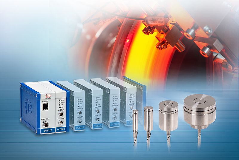
Micro-Epsilon now offers the robust, capacitive capaNCDT 6228 sensor system for displacement and distance measurements at ambient temperatures up to +800 °C. Its high temperature stability and exceptionally high linearity enable precise results even under difficult environmental conditions. The new capaNCDT 6228 capacitive sensor system consists of capaNCDT CSE/HT capacitive sensors and the capaNCDT 6228 controller.
For hot glass and metals
The sensor system is designed for high temperature applications up to +800 °C. Applications include measuring the thickness of glowing brake discs and monitoring the level of float glass. Up to four sensors can be connected simultaneously to the high-performance controller. The available sensors cover measuring ranges from 1 mm to 20 mm. A high temperature sensor cable compensates for interference from electrical or magnetic fields. In addition, measurement data is output in both analogue and digital form via modern interfaces such as Ethernet and EtherCAT.
Torque Sensor with Separate Sensing Head
Measuring in confined spaces without danger of damage to the electronics
Sensor Technology
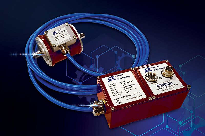
The new Sensor Technology TorqSense SGR530/540 series operates on a full four element strain gauge bridge. This uses four individual stain gauges affixed to the drive shaft; each measures the deflection of the shaft in a different direction as it rotates under load. The electronics collects readings from all four gauges and calculates the torque value.
The new range is designed to meet emerging user requirements, notably accurately recording transient torque spikes. In the past transducers didn’t have the bandwidth to capture these spikes, so they were ignored. However, advances in automation, continuous operation and the increasing need for accurate track and trace data has led to the need for more detailed measurement and analysis to give early warnings on deviations to plant engineers.
In use, a rotor mounted ultra-miniature microcontroller, powered by an inductive coil, measures the differential values in each strain gauge and transmits them back to the stator digitally, via the same coil. The SGR510/520 series transducers then use state of the art strain gauge signal conditioning techniques to provide a high bandwidth, low cost torque measuring solution with high overrange and overload capabilities.
Accurate with high overload limits
An advantage of the design of the SGR torque sensors is that they automatically compensate for any extraneous forces, such as bending moments, inadvertently applied to the sensor. They also offer high sensitivity and have a wide temperature tolerance, attributes that are required more and more and production machinery becomes more and more sophisticated and performance demands increase. Other advantages of the SGR range include elimination of noise pickup and signal corruption associated with slip rings and hard-wired solutions, a 400% mechanical overload limit with accurate torque measurement even at these extremes, and multipoint calibration to eliminate linearity errors within the sensor.
All units are accurate to +/-0.1% and resolution to +/-0.01% of the transducer’s full scale. Other features include an adjustable moving average filter, power supply range from 12VDC to 32VDC, user settable analogue output voltages, and RS232, USB, CANbus and Ethernet comms options.
Magnetic Field and Temperature Sensor with IO-Link
Condition monitoring sensor detects magnetic field changes on three axes and opens new application fields
Sensor Technology
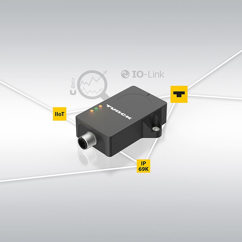
The CMMT 3-axis magnetic field/temperature sensor with IO-Link is the third sensor type that Turck has developed specifically for easy-to-use and retrofittable condition monitoring applications. It complements the existing range consisting of the CMVT vibration/temperature sensor and the CMTH for humidity and temperature measurements. The combined measurement of magnetic field and temperature with the CMMT enables simple detection of faults on motors or in processes with magnetic components. The new sensor also opens up applications that were previously impossible, such as the contactless detection of the rotation and movement of metal objects without visual contact.
App supported automation software
Thanks to its high sensitivity of five microtesla, the sensor also detects the earth's magnetic field, but can hide this if required by setting the parameters. The device outputs measured values individually or as a vector sum via IO-Link. Users can also assign two independent switching outputs. The CMMT supports the Smart Sensor Profile 4.1.4.
When commissioning the CMMT, users are supported by the Turck Automation Suite (TAS) Magnetic Field Monitor app. This application visualizes the sensor data live in the web browser and can be used via any Turck IO-Link master without additional software. The device functions are also set via TAS or other IODD interpreters. Besides the process values, additional information such as operating hours and switching cycles can also be output via the digital interface.
Optimised Designs to Match Your Application
Custom Optical Module for Cutting-Edge Imaging Systems
Test & Measurement, Vision & Identification
An optical module is a system of optical components that does more than just transmit a single image. For example, in interferometry - an optical module may use beamsplitters or prisms to create many images from a single image. Rob Watkinson, sales manager at Resolve Optics said “As a developer and supplier of custom lenses and optical systems to leading camera, sensor, and optical instrument manufacturers our aim is to help these customers keep at the forefront of the markets they serve through ongoing cooperative developments and providing continuous support.
He added “One such customer is Specialised Imaging – technological market leader in ultra-high-speed imaging and ballistic range cameras. Their SIM family of ultra-high-speed cameras are used by research laboratories around the world. These state-of-the-art cameras can capture up to thirty-two images at one billion frames per second enabling analysis of even the most fleeting of phenomena. To help the SIM camera range remain the ultra-high-speed multichannel imaging camera of choice for researchers working at the edge of what is possible and solving new applications challenges – Resolve Optics recently supplied a third generation ultra-high-speed camera optical module that is not only more user friendly but also provides improved state-of-the-art performance”.
In this latest development a key objective was to make it easier for Specialised Imaging to precisely align their sensors with the eight ports on the ultra-high-speed optical module. To provide this enhanced ease-of-use facility Resolve Optics developed a new sensor mounting system that enables easy adjustment of the whole port in x and y planes. This new adjustment system allows users of SIM ultra-high-speed imaging cameras to align their systems significantly quicker and with much more accuracy than was previously possible.
Managing Director of Specialised Imaging – Wai Chan commented “I am pleased to say that the Resolve Optics optomechanical design team has again risen to the challenge and designed a new and improved optical module that meets all of our specification needs of our SIM cameras.”
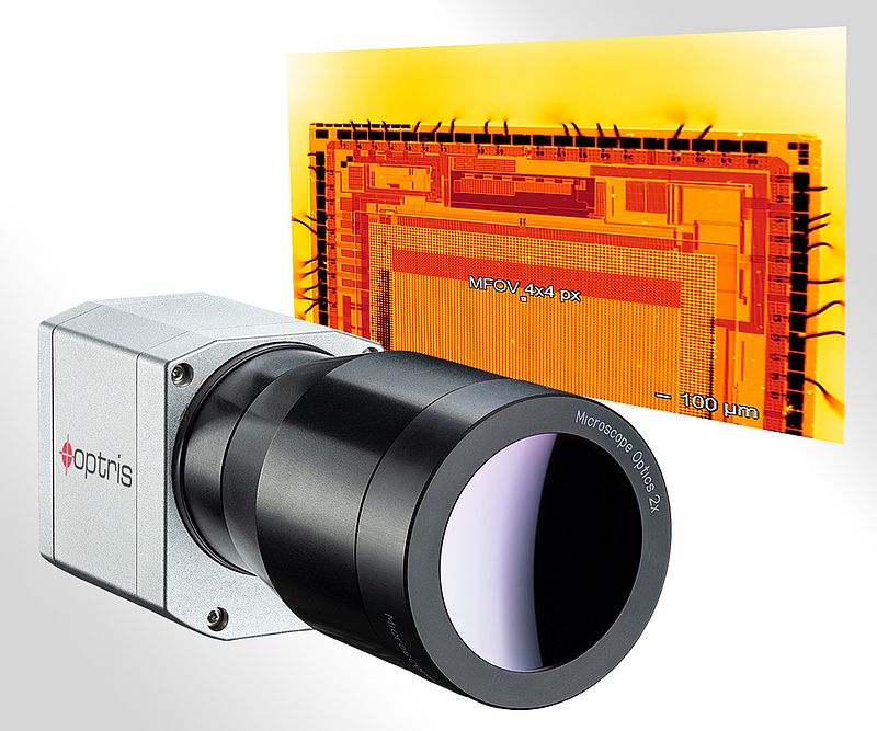
Infrared Camera with Microscope Optics
For temperature measurement with high resolution in the electronics industry
Vision & Identification
High temperatures negatively affect the life of electronic components and assemblies. This is due to the accelerated ageing of many semiconductor materials at high temperatures. Poor electrical connections due to increased contact resistance can cause this, for example. Complex semiconductor components such as processors can also experience elevated temperatures.
Resolution in the micrometer range
The PI 640i infrared camera from Optris is now able to capture infrared images of even complex structures using the new MO2X microscope optics with 2x magnification. For an accurate temperature measurement, 4x4 pixels are required (MFOV). This means that objects as small as 34 µm can now be measured. This means that even the smallest of structures can be analysed at the chip level. The thermal resolution of 80 mK is a very good value for this optic. The focus of the new optic makes it possible to work at a distance of 15 mm from the object to be measured. The optics on the PI Series infrared cameras are easily interchangeable, allowing the system to be used flexibly for different measurement tasks. Together with the supplied high quality microscope stand with fine adjustment, microelectronic assemblies can be easily inspected. The maximum resolution of the infrared camera is 640 x 480 pixels at a frame rate of 32 Hz. Even at 125 Hz, the PI 640i still delivers an impressive 640 x 120 pixels.
The license-free analysis software PIX Connect is included in the scope of delivery; alternatively, a complete SDK is also available.
The Rise of Modular Robots and the Importance of Drive Train Design
For lightweight robots, modular designs are increasingly popular thanks to the flexible deployment they enable for specialised tasks. Modular robots also enhancing the potential for system integrators and end users to develop their own designs. As part of an in-house robot build, optimising the drive train that powers and controls each joint is vital to the robot’s performance. The most effective way of achieving this is by developing the drive train as a complete module. This approach can also improve the efficiency of robot development overall.
Motors & Drives
As the requirements for robots continue to become increasingly specialised to task, the advantages of modular robots are to the fore. The ability to change their form and configuration, thanks to a combination of modules, as opposed to a fixed body, gives greater flexibility. This means that a modular robot can be reconfigured, or customised, as often and as quickly as is required. And should the robot fail, a replacement can be rapidly, and economically, provided.
In particular, there’s been a marked change towards modular designs in the industrial robot class at the level of lightweight robots and cobots. These smaller designs, typically handling loads between 3kg and 16kg, lend themselves to specialisation and the benefits of modularity. Their small size enables easier configuration, and for this payload range, there are a high volume of tasks that robots are required to fulfil. This is confirmed by reports in the growth of lightweight robots deployed, ranging from 20% to as high as 40% each year worldwide.
To facilitate the modular robot demand, there’s been a corresponding need for greater flexibility in robot control. Motion controller manufacturers and PLC manufacturers are increasingly offering kinematic libraries that enable robot control programming. This is allowing system integrators, as well as end users, ranging from car manufacturers to warehousing and delivery companies, to develop their own robots, instead of having to rely on dedicated robot manufacturers. The advantage is enhanced robotic control, more specific to their requirements, met with the flexibility to quickly respond to changing needs.
Motor design
Central to the increasing trend towards modular, lightweight robots, designed and built internally, is the need to power their kinematic motion. The motion system, or drive train, is responsible for moving and controlling each robotic joint. Just as a modular robot design must enable the flexibility to fulfil various specialised tasks, so too, the capability of the drive train has to match this need.
The motor itself is central to the drive train. To achieve the required high dynamic performance, necessary attributes include high torque density and low inertia, enabling rapid acceleration and deceleration. Smooth control of each robot joint is also essential, so the motor must ensure capabilities such as low cogging, minimising micro ripples and jerks during motor rotation.
For lightweight robots, a compact motor is also essential, which further emphasises the need for high torque density. A frameless design, like maxon’s EC frameless motor, enhances design integration, and its hollow shaft enables through routing of cables. Despite the motor’s small footprint, this design also answers the essential criteria of heat and energy efficiency.
The drive train
However, to optimise robot motion performance, not just the motor, but the complete drive train must be taken into consideration. The drive train, itself a module of the robot, typically comprises the motor, plus the gearhead, the encoder, which provides continual feedback on position and speed, as well as the motor’s position and speed controller. Like the motor, each of these components should be designed to enhance distinct performance criteria, yet the design of the drive train as a complete module is fundamental to optimising motion performance.
This requires correct dimensioning, and crucially, correct sizing, in terms of meeting the required motion output values, such as torque, speed, acceleration, and position profile. Often, the specialised requirements of modular robots for each individual application also mean that customisation of distinct motion components is also necessary. As these components perform together in concert, design changes to individual parts can have a subsequent impact on the operation of the motion system as a whole. Therefore, if customisation to any aspect is required, treating the drive train as a complete module is a more effective way of optimising both the motion performance as well as design integration.
To meet these objectives, the design stage should also include kinematic simulation. Creating a working, virtual model is vital to plan the robot’s motion path, ensuring that the desired kinematic profiles can be achieved, according to factors such as position, acceleration, and torque. Simulation is also crucial to ensure that the robot operates within safe limits for the protection of users, as well as the physical environment. This service can be provided by a motion designer like maxon, in conjunction with programming support for each axis of motion.
Optimising design efficiency
Designing and simulating the drive train as a module also makes the development process significantly more efficient. Most significantly, it removes the time required to develop and test the performance, compatibility, and integration of individual drive system components. In addition, it reduces demand on procurement teams. As a combined result, robots can be brought online more quickly.
The alternative approach of procuring distinct components might be attractive from an initial cost perspective. However, the development time required for in-house drive train engineering can make this process less cost-effective long term.
The greatest advantage of working with dedicated motion engineering expertise though, is the improved motion performance that can be achieved. Not only can this partnership increase a robot’s capabilities, but a tried and tested approach to drive train development can also enhance reliability, minimising downtime when the robots are deployed in the field.
When engaging a drive train designer, considering the impact that motion specification has on robot performance and design integration, ideally the motion engineers should be involved at the earliest opportunity. This will speed up development by minimising the volume of required iterations, and will quickly help achieve a finalised design.
Author: Roman Berger maxon Head of Business Development for Robotics
Servo Drive with New Synchronized Communication Protocols
For easier integration with third-party controllers
Motors & Drives
Kollmorgen has announced the latest update to its AKD2G servo drive. With the introduction of these new features, Kollmorgen has expanded its offering to include support for PROFINET IRT and Ethernet/IP with CIP Sync in addition to CANopen®, EtherCAT® and FSoE time-synchronised communication protocols. Each protocol has been rigorously tested with a wide range of motion controllers. Each has been certified by industry standards organisations. The update enables synchronised motion between multiple drives using a wide range of control architectures. The AKD2G is the ideal drive for applications that require high-precision coordination across multiple axes of motion due to its flexibility and high performance.
Optional safety up to SIL3
The drive offers industry-leading power density in a compact package and is easy to install - with single and dual axis variants available. Engineers can use single-cable Smart Feedback Device (SFD) or HIPERFACE® DSL connections, or choose from a wide range of other feedback devices. Finally, the drive offers optional SafeMotion® Monitor (SMM) firmware with a SIL3/PLe safety level to meet functional safety requirements and enable a wider range of applications.
The AKD2G paired with AKM2G motors is part of the 2G Motion System, a suite of motion products designed to work together for ultimate ease of setup and higher performance. Engineers also can take advantage of the drive’s compatibility with a wider range of controllers and feedback devices — or with other motors, as needed.
Compact Motion Control System for Brushless Motors
Integrated 12-bit encoder and controller with only 18 mm length
Motors & Drives
Integrated in the powerful brushless motors of the FAULHABER 22xx...BX4 family, the new Integrated Motion Controller 22xx…BX4 IMC, impresses users with its extensive range of functions and outstanding performance. Extension in length compared to the motor alone is 18mm only including a full featured servo controller and a 12-bit encoder. To top this, the full performance of the motors can be used in all different executions.
The version with RS232 interface is ideal for integration both from a PC or via an embedded master. The CANopen version is the perfect match for industrial automation networks. Being fully compliant with the CiA 402 servo drive standard allows direct support from typical PLCs. But even using the RS232 version several drives can be controlled using a single port of the master. Typical tasks like homing a drive can directly be executed by the integrated Motion Controller using its local digital and analog I/Os.
Alternatively, both versions can also be operated without a master in "stand-alone" mode. Its digital and analog I/Os can then be used very flexible for local control tasks or for discrete set-point and actual values. The compact 22xx…BX4 IMC can be combined with many products from the FAULHABER product range such as the compact GPT gearheads and the new FAULHABER 22L linear actuators.
Efficient and highly dynamic
The built-in current control automatically provides protection against overloading and there is also a diagnostic function. Supported are torque, velocity or position control according to the servo-drive standard. These features are complemented by low EMC emissions and the obligatory CE label.
The brushless motors with the new Integrated Motion Controller 22xx…BX4 IMC are available in two lengths, having first-class volume-to-performance ratio as well as highly dynamic control characteristics. They are suitable for a wide range of market segments such as medical and laboratory technology, automation technology, robotics or special industrial machinery.
Comprehensive Digitalization Offering Along the Drivetrain Value Chain
Siemens presents innovations for greater efficiency and sustainability from design to condition monitoring
Automation, Motors & Drives
At this year's Hannover Messe, Siemens has presented Siemens Xcelerator for Digital Drivetrain, its comprehensive and integrated digitalization offering along the drivetrain value chain comprised of two areas: Drivetrain Design (dimensioning and simulation) and Drivetrain Health (connectivity and optimization). Drivetrain Design includes engineering and simulation tools for the efficient dimensioning, validation, testing, virtual commissioning, and optimization of drivetrains in the design phase of a machine or system.
Drivetrain Health offers hardware- and software-based sensor and connectivity solutions for data acquisition as well as coordinated analysis software tools. These tools provide insights into the behavior of the drivetrain and enable powerful condition monitoring. Siemens is thus demonstrating how customers can combine the real and digital worlds of drive technology to achieve efficiency and sustainability along the entire drivetrain value chain.
For efficient selection, validation, virtual commissioning, and optimization of drive systems
In the area of simulation and virtual commissioning, Siemens is launching DriveSim Engineer, the successor to DriveSim Advanced. DriveSim Engineer makes it possible to create a digital twin of the drive in a virtual environment with all the parameters and configurations that correspond to the real drive. In addition to the new SINAMICS S210 series, the new SINAMICS G220 frequency converters are now also available in the tool. The digital twin technology and intuitive user interface allow users to simulate, commission, and optimize the behavior of drive systems in a virtual environment before installing them in the real world. This significantly increases efficiency and productivity in the engineering of drive systems and machines. Thanks to its integration in TIA Portal (Startdrive), DriveSim Engineer is a seamless part of (virtual) commissioning and makes training in additional tools superfluous. Users benefit from shorter commissioning times, more accuracy in detecting and resolving potential problems with drive systems, and real-time insights and analyses for improving the overall performance of drive systems.
Intelligent condition monitoring for a healthy drivetrain
Siemens is presenting two intelligent solution packages for high-performance condition monitoring: a cloud-based solution and a PC-based solution. The two complement each other and can be used according to requirements. With Drivetrain Analyzer Cloud, Siemens combines the two applications Analyze MyDrives and Sidrive IQ Fleet into one innovative app. In addition to a new user interface, Drivetrain Analyzer Cloud offers users the option of connecting various drive components such as frequency inverters, motors, or other rotating machines to a drivetrain and monitoring the drivetrain’s status. Another new product is the Connection Module IOT (CM IOT), which can be installed and put into operation in just a few minutes. Highlights include the improved, additional sensor technology, the new alternative energy concept via an external 24 V connection, and a housing and component update. The module measures raw data and automatically transfers it to the cloud. Drivetrain Analyzer Cloud provides immediate information about anomalies and specific error patterns such as bearing damage, imbalances, or misalignments, thereby helping to prevent unplanned downtime. The cost-efficient solution combines condition monitoring with decarbonization by supplying the user with important additional data and recommendations for action regarding CO₂ emissions, energy consumption, and energy costs. Another new feature is pump analytics, which Drivetrain Analyzer Cloud can use to calculate and analyze system efficiency and specific pump parameters.
In addition to the cloud solution, Siemens is also presenting another new product, a PC-based condition monitoring solution consisting of three components: the new VIB (Vibration) and FPP (Fast Process Parameters) (CM FPP) connection modules, the Drivetrain Analyzer X-Tools software, and the corresponding sensors and sensor cables. The CM VIB and CM FPP connectivity modules record vibration and analog signals at a sampling rate of 96 kHz. All sensor information can be recorded and transmitted synchronously. Now users can also analyze high-speed, intermittent machines such as automotive presses, cranes, or machine tools with two synchronous axes. Drivetrain Analyzer X-Tools is an expert tool for highly dynamic data acquisition up to 192 kHz as well as for manual data analysis. Because X-Tools can connect to almost any data source, users can ideally use X-Tools as an analytics toolbox to link their own analytics with elements of a preconfigured library. For example, the software can be used to monitor bearing temperature, housing vibrations, and oil lubrication, meaning pressure and flow, in heavy machinery equipped with plain bearings. In this way, Drivetrain Analyzer X-Tools and the new connectivity modules contribute to higher machine availability, better performance, and a longer system service life.
Modular Encoders for Precise Motor Control
Compact, flat, and lightweight models with high resolution and fine accuracy
Motors & Drives, Sensor Technology
Lika Electronic's AMM33 miniature encoder is equipped with a 6 mm blind hollow shaft and is ideally suited for integration into very small size motors. The SMAR1 off-axis encoder fits perfectly into hollow shaft motors and axes with larger diameter up to 18 mm.
Energy harvesting technology
The AMM33 is absolute and multiturn and integrates the Energy Harvesting Technology for battery- and gear-less operation. It can be equipped with SSI and BiSS interfaces. The singleturn resolution is up to 18 bits, the number of turns is up to 24 bits.
The SMAR1 has both incremental and absolute outputs (Line Driver, SSI, BiSS, and SPI). Incremental version offers a resolution up to 65,536 PPR and additional UVW commutation signals. The absolute version has a resolution between 16 and 35 bits and additional TTL signals for speed control.
To fulfil specific customer requirements mechanical and electrical characteristics can be customized.
3
3DS DELMIA 9A
ABB Ltd 12 Aetina Europe B.V. 8B
Baykon Endüstriyel Kontrol Sistemleri San. Ve Tic. A.S 15 Beckhoff Automation GmbH 12D
Delta Electronics (Netherlands) B.V. 8E
ELGi Compressors 11H
J
K
Kollmorgen Europe GmbH 20L
M
O
P
Phoenix Contact GmbH & Co. KG 13R
Resolve Optics Ltd 17 Rohde & Schwarz GmbH & Co 13S
Sensor Technology Ltd 16 Sfera Labs S.r.l. 7 Siemens AG 21T
Titan Enterprises Ltd 15U
U.I. LAPP GmbH 6TIMGlobal Media BV
Rue de Stalle 140 - 3ième étage - 1180 Uccle - Belgium
o.erenberk@tim-europe.com - www.ien.eu
- Editorial Director:Orhan Erenberko.erenberk@tim-europe.com
- Editor:Kay Petermannk.Petermann@tim-europe.com
- Editorial Support / Energy Efficiency:Flavio Steinbachf.steinbach@tim-europe.com
- Associate Publisher:Marco Marangonim.marangoni@tim-europe.com
- Production & Order Administration:Francesca Lorinif.lorini@tim-europe.com
- Website & Newsletter:Marco Prinarim.prinari@tim-europe.com
- Marketing Manager:Marco Prinarim.prinari@tim-europe.com
- President:Orhan Erenberko.erenberk@tim-europe.com
Advertising Sales
Tel: +41 41 850 44 24
Tel: +32-(0)11-224397
Fax: +32-(0)11-224397
Tel: +33 1 842 00 300
Tel: +49-(0)9771-1779007
Tel: +39-02-7030 0088
Turkey
Tel: +90 (0) 212 366 02 76
Tel: +44 (0)79 70 61 29 95
John Murphy
Tel: +1 616 682 4790
Fax: +1 616 682 4791
Incom Co. Ltd
Tel: +81-(0)3-3260-7871
Fax: +81-(0)3-3260-7833
Tel: +39(0)2-7030631
- WebMag December 2024 IEN Europe presents Industry News, Products and Solutions for industrial decision makers in the pan-European B2B market.
- IEN Europe SPS WebMag 2024 IEN Europe special issue for sps 2024 in Nuremberg, November 12 to 14.
- IEN Europe WebMag August 2024 IEN Europe presents Industry News, Products and Solutions for industrial decision makers in the pan-European B2B market.
- WebMag IEN Europe July 2024 IEN Europe presents Industry News, Products and Solutions for industrial decision makers in the pan-European B2B market.
- IEN Europe May 2024 IEN Europe presents Industry News, Products and Solutions for industrial decision makers in the pan-European B2B market.
- WebMag HANNOVER MESSE 2024 Special issue for Hannover Messe 2024, April 21 - 26
- WebMag January/February 2024 IEN Europe presents Industry News, Products and solutions for industrial decision makers in the pan-European B2B market.
- WebMag December 2023 Highlights Products and Solutions sps and from 2023
- IEN Europe November Webmag Special SPS As the industrial world gears up for the 2023 SPS Show in Nuremberg, attendees and exhibitors alike are eagerly awaiting the opportunity to delve into the latest trends and innovations that promise to reshape the future of industrial automation and techno
- IEN Europe April WebMag Throw an eye to this web magazine dedicated to the coming Hannover Messe 2023! We wish to see you there as well. Have a nice and interesting reading
- IEN Europe Jan/Feb 2023 Webmag Dear readers, Happy New Year to you! IEN Europe is coming back this new year with a special focus on robotics and digital automation.
- #6 AI IEN - December 2020 Discover our latest edition of our digital magazine: AI IEN!
- IEN Europe December Last issue of 2020, IEN Europe December highlights the key trends in the IoT & e-mobility, Automotive, and Identification & Vision Systems fields.
- IEN Europe November - SPS Webmag Discover in this digital issue the best technology showcased at the upcoming SPS virtual exhibition!
- #5 AI IEN - October 2020 We are delighted to release the fifth issue of AI IEN! With a specific focus on Artificial Intelligence (AI) applied to the industrial field, AI IEN aims to become a point of reference for all AI professionals.
- Covid-19 Special e-magazine Don't miss our new issue on Covid-19 to discover the most innovative Industrial answers to the pandemic.
- #4 AI IEN - June 2020 Don’t miss the fourth issue of AI IEN! With a specific focus on Artificial Intelligence (AI) applied to the industrial field, AI IEN aims to become a point of reference for all AI professionals.
- #3 AI IEN - April 2020 Don’t miss the third issue of AI IEN! With a specific focus on Artificial Intelligence (AI) applied to the industrial field, AI IEN aims to become a point of reference for all AI professionals.
- #2 AI IEN - February 2020 Don’t miss this new issue of AI IEN! With a specific focus on Artificial Intelligence (AI) applied to the industrial field, AI IEN aims to become a point of reference for all AI professionals.
- SPS Webmag November Discover in this digital issue the best technology showcased at the upcoming SPS - Smart Production Solutions 2019!
- #1 AI IEN - September 2019 We are delighted to announce the launch of our new digital magazine AI IEN. With a specific focus on Artificial Intelligence (AI) applied to the industrial field, AI IEN aims to become a point of reference for all AI professionals.
